Atari ST desktop with Doom shortcut

Running DOOM On An Atari ST

If you grew up with a beige Atari ST on your desk and a faint feeling of being left out once Doom dropped in 1993, brace yourself — the ST strikes back. Thanks to [indyjonas]’s incredible hack, the world now has a working port of DOOM for the Atari STe, and yes — it runs. It’s called STDOOM, and even though it needs a bit of acceleration or emulation to perform, it’s still an astonishing feat of retro-software necromancy.

[indyjonas] did more than just recompile and run: he stripped out chunks of PC-centric code, bent GCC to his will (cheers to Thorsten Otto’s port), and shoehorned Doom into a machine never meant to handle it. That brings us a version that runs on a stock machine with 4MB RAM, in native ST graphics modes, including a dithered 16-colour mode that looks way cooler than it should. The emotional punch? This is a love letter to the 13-year-old Jonas who watched Doom from the sidelines while his ST chugged along faithfully. A lot of us were that kid.

Sound is still missing, and original 8MHz hardware won’t give you fluid gameplay just yet — but hey, it’s a start. Want to dive in deeper? Read [indyjonas]’ thread on X.

The Screamer Is Just Like The Clapper But Even More Annoying

Remember The Clapper? It was a home automation tool (of sorts) that let you turn appliances on and off by clapping. [Kevin O’Connor] has built something rather similar, if more terrifying. It’s called The Screamer.

The build is based around a Sonoff S31 smart switch. [Kevin] selected an off-the-shelf device because he wanted something that was safe to use with mains power out of the box. But specifically, he selected the S31 because it has an ESP8266 inside that’s easy to reprogram with the aid of ESPHome. He ended up hooking up a whole extra ESP32 with an INMP441 microphone over I2S to do the scream detection. This was achieved with a simple algorithm that looked for high amplitude noises with lots of energy in the 1000 – 4000 Hz frequency range. When a scream is detected, it flips a GPIO pin which is detected by the S31, which then toggles the state of the smart switch in turn. Job done.

It’s a simple project that does exactly what it says on the tin. It’s The Screamer! If you’d like to learn more about the original Clapper that inspired this build, we’ve looked at that before, too. Meanwhile, if you’re cooking up your own excuses to scream at the lights and walls in your home, please only notify the tipsline if it has something vaguely to do with electronics or hackery.

A Single Chip Computer For The 8051 Generation

The Intel 8051 series of 8-bit microcontrollers is long-discontinued by its original manufacturer, but lives on as a core included in all manner of more recent chips. It’s easy to understand and program, so it remains a fixture despite much faster replacements appearing.

If you can’t find an original 40-pin DIP don’t worry, because [mit41301] has produced a board in a compatible 40-pin format. It’s called the single chip computer not because such a thing is a novelty in 2025, but because it has no need for the support chips which would have come with the original.

The modern 8051 clone in use is a CH558 or CH559, both chips with far more onboard than the original. The pins are brought out to one side only of the board, because on the original the other side would interface with an external RAM chip. It speaks serial, and can be used through either a USB-to-serial or Bluetooth-to-serial chip. There’s MCS-BASIC for it, so programming should be straightforward.

We can see the attraction of this board even though we reach for much more accomplished modern CPUs by choice. Several decades ago the original 8051 on Intel dev boards was our university teaching microcontoller, so there remains here a soft spot for it. We certainly see other 8051 designs, as for example this Arduino clone.

Diagram showing the structure of the base.

Magic On Your Desk Via MagLev Toy

Magnets aren’t magic, but sometimes you can do things with them to fool the uninitiated — like levitating. [Jonathan Lock] does that with his new maglev desk toy, that looks like at least a level 2 enchantment.

This levitator is USB-powered, and typically draws 1 W to 3 W to levitate masses between 10 g and 500 g. The base can provide 3 V to 5 V inductive power to the levitator to the tune of 10 mA to 50 mA, which is enough for some interesting possibilities, starting with the lights and motors [Jonathan] has tried.

In construction it is much like the commercial units you’ve seen: four permanent magnets that repel another magnet in the levitator. Since such an arrangement is about as stable as balancing a basketball on a piece of spaghetti, the permanent magnets are wrapped in control coils that pull the levitator back to the center on a 1 kHz loop. This is accomplished by way of a hall sensor and an STM32 microcontroller running a PID loop. The custom PCB also has an onboard ESP32, but it’s used as a very overpowered USB/UART converter to talk to the STM32 for tuning in the current firmware.

If you think one of these would be nice to have on your desk, check it out on [Jonathan]’s GitLab. It’s all there, from a detailed build guide (with easy-to-follow animated GIF instructions) to CAD files and firmware. Kudos to [Jonathan] for the quality write-up; sometimes documenting is the hardest part of a project, and it’s worth acknowledging that as well as the technical aspects.

We’ve written about magnetic levitation before, but it doesn’t always go as well as this project. Other times, it very much does. There are also other ways to accomplish the same feat, some of which can lift quite a bit more.

Building A DIY Chicken Incubator

If you want to keep eggs warm to hatch, you’ll need an incubator. You could buy one off the shelf, but they’re not so complex — just a nicely-controlled warm box you could easily whip up yourself. As it turns out, that’s precisely what [RCLifeOn] did. 

The incubator is built out of wooden panels screwed together to make a simple box. The frame of the front door is also wood, but it features 3D printed hinges and handles, because that’s the easiest way to make hardware when you’re a printing wizard like [RCLifeOn].

The box is fitted with controls for humidity and temperature to ensure the best possible conditions for hatching chicken eggs inside. As you might have guessed, a heated bed from a 3D printer was used to control the temperature inside. As for humidity, a sensor tracks the conditions in the box, and triggers an ultrasonic mister to increase the level as necessary. There’s also a little motion introduced via a moving platform run by a motor and some step-down gearing, which apparently aids in the hatching process.

[RCLifeOn] calls it “a machine that creates life,” and that honestly sounds about fair. We’ve seen similar projects along these lines before, too.

Continue reading “Building A DIY Chicken Incubator”

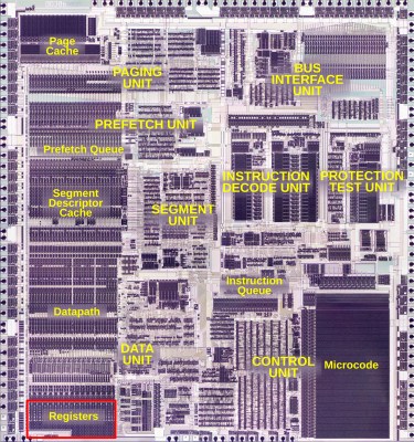
The 386's main register bank, at the bottom of the datapath. The numbers show how many bits of the register can be accessed. (Credit: Ken Shirriff)

The Convoluted Way Intel’s 386 Implemented Its Registers

The fact that modern-day x86 processors still pretty much support the same operating systems and software as their ancestors did is quite a feat. Much of this effort had already been accomplished with the release of the 80386 (later 386) CPU in 1985, which was not only the first 32-bit x86 CPU, but was also backwards compatible with 8- and 16-bit software dating back to the 1970s. Making this work transparently was anything but straightforward, as [Ken Shirriff]’s recent analysis of the 80386’s main register file shows.

Labelled Intel 80386 die shot. (Credit: Ken Shirriff)

Using die shots of the 386’s registers and surrounding silicon, it’s possible to piece together how backwards compatibility was implemented. The storage cells of the registers are implemented using static memory (SRAM) as is typical, with much of the register file triple-ported (two read, one write).

Most interestingly is the presence of different circuits (6) to support accessing the register file for 8-, 16- or 32-bit writes and reads. The ‘shuffle’ network as [Ken] calls it is responsible for handling these distinct writes and reads, which also leads to the finding that the bottom 16 bits in the registers are actually interleaved to make this process work smoother.

Fortunately for Intel (and AMD) engineers, this feat wouldn’t have to be repeated again with the arrival of AMD64 and x86_64 many years later, when the 386’s mere 275,000 transistors on a 1 µm process would already be ancient history.

Want to dive even deeper in to the 386? This isn’t the first time [Ken] has looked at the iconic chip.

Train With Morse Master

Morse code can be daunting to learn when you’re new to the game, particularly if you need it to pass your desired radio license. However, these days, there are a great many tools to aid in the learning process. A good example is the Morse Master from [Arnov Sharma].

The Morse Master is a translator for Morse code, which works in two ways. You can access it via a web app, and type in regular letters which it then flashes out as code on its in-built LEDs. Alternatively, you can enter Morse manually using the physical key, and the results will be displayed on the web app. The Morse key itself is built into the enclosure using 3D printed components paired with a Cherry-style keyboard switch. It’s perhaps not the ideal solution for fast keying, with its limited rebound, but it’s a quick and easy way to make a functional key for practice purposes. If you want to go faster, though, you might want to upgrade to something more capable. We’d also love to see a buzzer added, since Morse is very much intended as an auditory method of communication.

We’ve seen some other great Morse code trainers before, too. If you’ve trained yourself in this method of communication, don’t hesitate to share your own learning tips below.

Continue reading “Train With Morse Master”