The 8051 was an 8-bit Harvard-architecture microcontroller first put out by Intel in 1980. They’ve since discontinued that line, but it lives on in the low-cost STC8 family of chips, which is especially popular in Asia. They’re cheap as, well, chips — under 1$ — but lack compatibility with modern toolchains. If you’re happy with C, then you’re fine, but if you want to plus-plus it up and use all those handy-dandy shortcuts provided by the Arduino ecosystem, you’re out of luck. Or rather, you were, until [Bùi Trịnh Thế Viên] aka [thevien257] came up with a workaround.
The workaround is delightfully Hack-y. One could, conceivably, port a compiler for Arduino’s Wiring to the 8051, but that’s not what [Viên] did, probably because that would be a lot of work. There isn’t even a truly modern toolchain to put plain C on this chip. Instead, [Viên] started with rv51, a RISC-V emulator written in 8051 assembly language by [cryozap]. RISC-V is a lot easier to work with and, frankly, a more useful skill to build up.
The Intel 8051 series of 8-bit microcontrollers is long-discontinued by its original manufacturer, but lives on as a core included in all manner of more recent chips. It’s easy to understand and program, so it remains a fixture despite much faster replacements appearing.
If you can’t find an original 40-pin DIP don’t worry, because [mit41301] has produced a board in a compatible 40-pin format. It’s called the single chip computer not because such a thing is a novelty in 2025, but because it has no need for the support chips which would have come with the original.
The modern 8051 clone in use is a CH558 or CH559, both chips with far more onboard than the original. The pins are brought out to one side only of the board, because on the original the other side would interface with an external RAM chip. It speaks serial, and can be used through either a USB-to-serial or Bluetooth-to-serial chip. There’s MCS-BASIC for it, so programming should be straightforward.
We can see the attraction of this board even though we reach for much more accomplished modern CPUs by choice. Several decades ago the original 8051 on Intel dev boards was our university teaching microcontoller, so there remains here a soft spot for it. We certainly see other 8051 designs, as for example this Arduino clone.
Most of us are familiar with the Arduino Uno, a starting place for electronics projects since 2010. But what if the Arduino Uno was released in 1980? You’d probably get something like [ElectroBoy]’s 8051-based Arduino Uno.
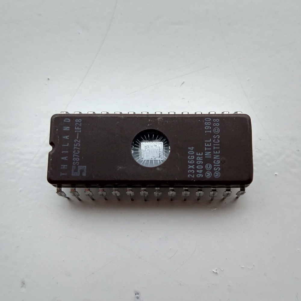
Close-up shot of the 87C752, an 8051 with EPROM
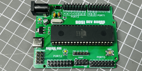
The Arduino Uno-compatible board has an MCS-51 (often called 8051 instead) instead of the usual ATmega328P/ATmega168. Specifically, [ElectroBoy] uses the AT89S52. Like the ATmega microcontrollers, the AT89S52 has an 8-bit CPU with a Harvard architecture and very similar GPIO capabilities. Unlike the ATmega, however, the original MCS-51 has a CISC CPU (as opposed to ATmega being RISC) and a release date about 36 years earlier.
The board itself also has some differences from the original Arduino Uno. First of all, it has a USB type-C port, which is definitely a bonus. Secondly, it’s simpler: No USB-UART (which also means no USB programming), a different pin layout (Arduino shields likely won’t fit) and more I/Os than the ATmegas have. Sure, it’s not as practical as an actual Arduino Uno, but it’s definitely cool for our retrocomputing nerds.
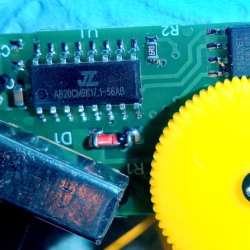
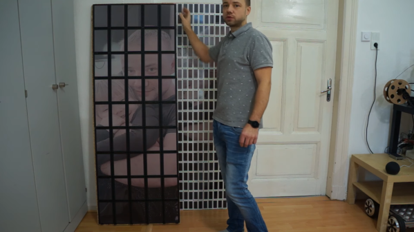
Just like the clock clock of old, there’s something magical about a giant wall of smaller pieces working together to make a larger version of that thing. The E-Paper Wall 2.0 by [Aaron Christophel] is no exception as it has now upgraded from 2.9″ to 7.4″ screens.
On the 1.0 version, the bezels made it harder to make out the image. The larger screens still have bezels but the larger screen area makes it much easier to make out the image. 3D-printed clips hold the displays onto a plywood backer. We can marvel that e-ink price tags brought the price of e-ink down so that building a wall is still expensive but not eye-wateringly so. The 5×9 array likely uses a module sold on DigiKey for $47 each.
So aside from being willing to drop some money on a custom piece of art, what’s special about this? The real magic comes with the firmware and tooling that [Aaron] developed to flash custom firmware onto each of the 45 displays. A 100MHz ZBS243/SEM9110 8051-based controller lives inside each display and [Aaron] even has a Ghidra plugin to reverse-engineer the existing firmware. It only has 64kb of flash onboard, so [Aaron] devised a clever compression technique that enabled him to store complex images on the displays. A 3D-printed jig with pogo pins means flashing them doesn’t require soldering pins or headers, just drop it on and flash it with an Arduino with a helpful library [Aaron] wrote. A central station communicates with the various displays over ZigBee to send image updates.
The 8051 has a funny way of showing up in projects like this portable soldering iron or the TV Guardian. In many ways, it is a boon for us hackers as it makes it easier to reverse engineer and write new custom firmware when so many devices use the same architecture.
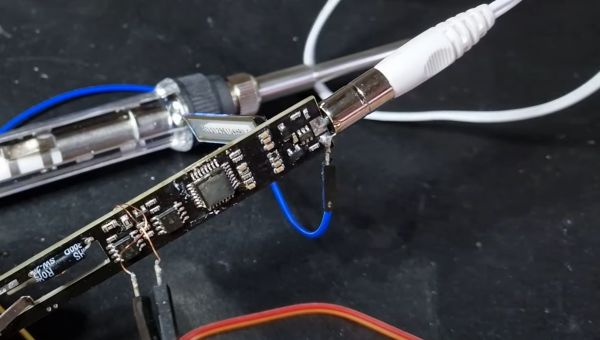
With soldering irons being so incredibly useful, and coming on the heels of the success of a range of portable, all-in-one soldering irons from the likes of Waveshare and Pine64, it’s little wonder that you can get such devices for as little as 10 – 15 Euro from websites like AliExpress. Making for both a great impulse buy and reverse-engineering target, [Aaron Christophel] got his mittens on one and set to work on figuring out its secrets.
The results are covered in a brief video, as well as a Twitter thread, where this T12 soldering iron’s guts are splayed around and reprogrammed in all their glory. Despite the MCU on the PCB having had its markings removed, some prodding and poking around revealed it to be an STC8H3K62S2, an 8051-based MCU running at a blistering 11 MHz. As a supported PlaformIO target, reprogramming the MCU wasn’t too complicated after wiring up a USB-TTL serial adapter.
Completing this initial foray into these cheap T12 soldering irons is the GitHub repository, which contains the pin-outs, wiring diagrams and further information. Although [Aaron] indicates that he’ll likely not pursuing further development, the mixed responses by people to the overall quality of the firmware on the as-purchased T12 may inspire others to give it a shake.
Nobody likes opening up a hacking target and finding a black epoxy blob inside, but all hope is not lost. At least not if you’ve got the dedication and skills of [Jeroen Domburg] alias [Sprite_tm].
It all started when [Big Clive] ordered a chintzy Chinese musical meditation flower and found a black blob. But tantalizingly, the shiny plastic mess also included a 2 MB flash EEPROM. The questions then is: can one replace the contents with your own music? Spoiler: yes, you can! [Sprite_tm] and a team of Buddha Chip Hackers distributed across the globe got to work. (Slides here.)
[Jeroen] started off with binwalk and gets, well, not much. The data that [Big Clive] dumped had high enough entropy that it looks either random or encrypted, with the exception of a couple tiny sections. Taking a look at the data, there was some structure, though. [Jeroen] smelled shitty encryption. Now in principle, there are millions of bad encryption methods out there for every good one. But in practice, naive cryptographers tend to gravitate to a handful of bad patterns.
Bad pattern number one is XOR. Used correctly, XORing can be a force for good, but if you XOR your key with zeros, naturally, you get the key back as your ciphertext. And this data had a lot of zeros in it. That means that there were many long strings that started out the same, but they seemed to go on forever, as if they were pseudo-random. Bad crypto pattern number two is using a linear-feedback shift register for your pseudo-random numbers, because the parameter space is small enough that [Sprite_tm] could just brute-force it. At the end, he points out their third mistake — making the encryption so fun to hack on that it kept him motivated!
Decrypted, the EEPROM data was a filesystem. And the machine language turned out to be for an 8051, but there was still the issue of the code resident on the microcontroller’s ROM. So [Sprite_tm] bought one of these flowers, and started probing around the black blob itself. He wrote a dumper program that output the internal ROM’s contents over SPI. Ghidra did some good disassembling, and that let him figure out how the memory was laid out, and how the flow worked. He also discovered a “secret” ROM area in the chip’s flash, which he got by trying some random functions and looking for side effects. The first hit turned out to be a memcpy. Sweet.
[Neil555]’s Rosetta StoneMeanwhile, the Internet was still working on this device, and [Neil555] bought a flower too. But this one had a chip, rather than a blob, and IDing this part lead them to an SDK, and that has an audio suite that uses a derivative of WMA audio encoding. And that was enough to get music loaded into the flower. (Cue a short rick-rolling.) Victory!
Well, victory if all you wanted to do was hack your music onto the chip. As a last final fillip, [Sprite_tm] mashed the reverse-engineered schematic of the Buddha Flower together with [Thomas Flummer]’s very nice DIY Remoticon badge, and uploaded our very own intro theme music into the device on a badge. Bonus points? He added LEDs that blinked out the LSFR that were responsible for the “encryption”. Sick burn!
Editor’s Note: This is the last of the Remoticon 2 videos we’ve got. Thanks to all who gave presentations, to all who attended and participated in the lively Discord back channel, and to all you out there who keep the hacking flame alive. We couldn’t do it without you, and we look forward to a return to “normal” Supercon sometime soon.
The first optical mice had to be used on a specially printed mousepad with a printed grid that the four-quadrant infrared sensor could detect. Later, mice swapped the infrared sensor for an optoelectric module (essentially a tiny, very low-resolution camera) and a powerful image processing. [8051enthusiast] was lying in bed one day when they decided to crack the firmware in their gaming mouse and eventually start streaming frames from the camera inside.
Step one was to analyze the protocol between the mouse and the host machine. Booting up a Windows VM and Wireshark allowed him to capture all the control transfers to the USB controller. Since it was a “programmable” gaming mouse that allowed a user to set macros, [8051enthusiast] could use the control transfers that would normally query that macro that had been set to return the memory at an arbitrary location. A little bit of tinkering later, and he now had a dump of the firmware. Looking at the most abundant bytes, it seems to match a profile similar to the Intel 8051. In a fascinating blur of reverse engineering, he traced the main structure of the program back from the function that sets the LED colors for the scroll wheel (which is dependent on the current DPI setting). Unfortunately, the firmware prevented the same macro mechanism from writing to arbitrary locations.
Looking through the code, a good old buffer overflow exploit seemed possible, but it caused the system to reset via watchdog. So he took another approach, invoking recovery mode and loading an entirely new firmware on the device, which a set_report control transfer can invoke.
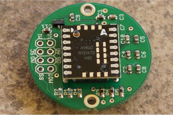
Next, he moved onto the ADNS-9800 optical sensor (pictured in the top image provided by JACK Enterprises), which had a large encrypted blob in the firmware. Some poking around and deduction lead to a guess that the optical sensor was another 8051 system. With some clever reasoning and sheer determination, [8051enthusiast] was able to crack the XOR stream cipher encryption with a program that showed him versions of the disassembled assembly and allowed him to pick the one that was the most likely. With the firmware decrypted, he was able to see the encryption code and confirm his deducted algorithm.
With the sensor now cracked open, it was onto the 30 x 30 240 fps video stream. The sensor communicates over SPI, and the USB controller has to bit-bang the connection as it doesn’t have the hardware. Putting two custom firmware images on with a few extra functions was easy enough, but the 7 fps was somewhat lacking. The first optimization was loop unrolling and removing some sleeps in the firmware, which bought it up to 34 fps. By measuring the cycle counts of individual instructions, he was able to find some alternatives such as a mov instead of a setb that took one less cycle. Going from a 17 cycle loop to an 11 cycle loop and some other optimizations gave him 54 fps. Not content to stop there, he modified the ADNS-9800 firmware to continuously sample rather than waiting for the USB controller to finish processing. While this yielded 100 fps, there was still more to do: image compression. At a whopping 230 fps, [8051enthusiast] decided to call it done.
However, there was one last thing he wanted to do: control the mouse with the video stream. Writing some image processing into his Python-based program that received the image files allowed him to use the mouse, however impractically.
All in all, it’s an incredible journey by [8051enthusiast], and we would highly recommend reading the whole journey yourself. This isn’t the first time he’s modified the firmware of 8051-based devices, such as modifying the firmware of the WiFi chipset in his laptop.


 It all started when [Big Clive] ordered a chintzy Chinese musical meditation flower and found a black blob. But tantalizingly, the shiny plastic mess also included a 2 MB flash EEPROM. The questions then is: can one replace the contents with your own music? Spoiler: yes, you can! [Sprite_tm] and a team of Buddha Chip Hackers distributed across the globe got to work. (
 Bad pattern number one is XOR. Used correctly, XORing can be a force for good, but if you XOR your key with zeros, naturally, you get the key back as your ciphertext. And this data had a lot of zeros in it. That means that there were many long strings that started out the same, but they seemed to go on forever, as if they were pseudo-random. Bad crypto pattern number two is using a linear-feedback shift register for your pseudo-random numbers, because the parameter space is small enough that [Sprite_tm] could just brute-force it. At the end, he points out their third mistake — making the encryption so fun to hack on that it kept him motivated!