While most people who build their own computer from chips want the finished product to do something useful, there’s something to be said about a huge bank of switches and a bunch of blinkenlights. They’re incredibly simple – most of the time, you don’t even need RAM – and have a great classic look about them.
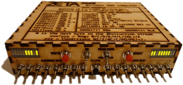
[Jim] wanted to build one of these computers and wound up creating a minimal system with switches and blinkenlights. It’s based on the Z80 CPU, has only 256 bytes of RAM, and not much else. Apart from a few extra chips to output data and address lines to LEDs and a few more to read switches, there are only two major chips in this computer.
With the circuit complete, [Jim] laser cut a small enclosure big enough to house his stripboard PCB, the switches and LEDs, and a few buttons to write to an address, perform a soft reset, and cycle the clock. One of the most practical additions to this switch/blinkenlight setup is a hand crank. There’s no crystal inside this computer, and all clock cycles are done manually. Instead of pushing a button hundreds of times to calculate something. [Jim] added a small hand crank that cycles the clock once per revolution. Crazy, but strangely practical.
[Jim] made a demo video of his computer in action, demonstrating how it’s able to calculate the greatest common divisor of two numbers. You can check that video out below.
Continue reading “A Z80 Computer With Switches And Blinkenlights”

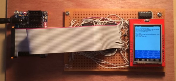
 The circuit is constructed with a $10 eBay special FPGA, the Cyclone II EP2C5. Other than that, it’s just some Flash, some RAM, a display, and a whole lot of wire.