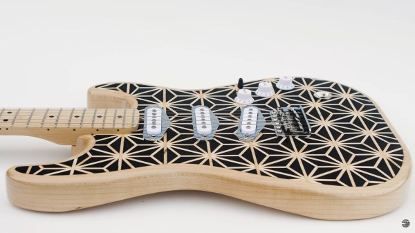
Magic 8-Ball Gets A Modern Makeover

Back in 2012, [sjm4306] was surprised when his breadboard rendition of the classic “Magic 8-Ball” popped up on Hackaday. If he had known the project was going to be enshrined on these hallowed pages, he might have tidied things up a bit. Now with nearly a decade of additional electronics experience, he’s back and ready to show off a new and improved version of the project.

The 3D printed case helps sell the look.

Conceptually, not much has changed from the original version. Press a button, get a random response. But on the whole the project is more refined, and not just because it’s moved over to a custom PCB.

The original version used a PIC16F886 with a charge controller and experimental RTC, but this time around [sjm4306] has consolidated all the functionality into the ATmega328P and is powering the whole thing with a simple CR2032 coin cell. As you can see in the video after the break, assembly is about as quick and straight-forward as it gets.

As with the original, there’s no accelerometer onboard. If you want to see a new message from your mystic companion, you’ve got to hold the button to “shake” the ball. A timer counts how long the button is held down, which in turn seeds the pseudorandom number generator that picks the response. Since each person will naturally hold the button for a slightly different amount of time, this keeps things from getting repetitive.

We don’t often see creators revisit their projects from the olden days, but we’d certainly like to. Consider this an open invitation to any hacker who wants to show off how much they’ve refined their skills; do-overs are always welcome here at Hackaday.

Continue reading “Magic 8-Ball Gets A Modern Makeover”

Printed Circuits, 1940s Style

A presentation this month by the Antique Wireless Museum brought British engineer and inventor John Sargrove (1906-1974) to our attention. If you’ve ever peeked inside old electronics from days gone by, you’ve no doubt seen point-to-point wiring and turret board construction. In the 60s and 70s these techniques eventually made way for printed circuit boards which we still use today. But Mr Sargrove was way ahead of his time, having already invented a process in the 1930s to print circuits, not just boards, onto Bakelite. After being interrupted by the war, he formed a company Electronic Circuit Making Equipment (ECME) and was building broadcast radio receivers on an impressive automatic production line.

Mr. Sargrove’s passion was making radios affordable for everyone. But to achieve this goal, he had to make large advances manufacturing technology. His technique of embedding not only circuit traces, but basic circuit elements like resistors, capacitors, and inductors directly into the substrate foresaw techniques being applied decades later in integrated circuit design.  He also developed a compact vacuum tube which could be used in all circuits of a radio, called an “All-stage Valve“. Equally important was his futuristic automatic factory, which significantly reduced the number of factory workers needed to make radios from 1500 to 50. Having completed the radio design, he was also developing a television receiver using the same concepts. Unfortunately, ECME was forced into liquidation when a large order from India was cancelled upon declaration of independence in 1947.

You really must watch the video below. There are many bits and pieces of modern factory automation which we still use today, yet their implementation using 1940s techniques and technology is fascinating. Further reading links after the video. Thanks to [Mark Erdle] for the tip.

Continue reading “Printed Circuits, 1940s Style”

Taking Over The Amazing Control Panel Of A Vintage Video Switcher

Where does he get such wonderful toys? [Glenn] snagged parts of a Grass Valley Kalypso 4-M/E video mixer switcher control surface from eBay and since been reverse engineering the button and display modules to bend them to his will. The hardware dates back to the turn of the century and the two modules would have been laid out with up to a few dozen others to complete a video mixing switcher console.

[Glenn’s] previous adventures delved into a strip of ten backlit buttons and gives us a close look at each of the keyswitches and the technique he used to pull together his own pinout and schematic of that strip. But things get a lot hairier this time around. The long strip seen above is a “machine control plane” module and includes a dozen addressible character displays, driven by a combination of microcontrollers and FPGAs. The square panel is a “Crosspoint Switch Matrix” module include eight individual 32 x 32 LCDs drive by three dedicated ICs that can display in red, green, or amber.

[Glen] used an STM8 Nucleo 64 to interface with the panels and wrote a bit of code to help map out what each pin on each machine control plane connector might do. He was able to stream out some packets from the plane that changed as he pressed buttons, and ended up feeding back a brute-force of that packet format to figure out the LED display protocols.

But the LCDs on the crosspoint switch were a more difficult nut to crack. He ended up going back to the original source of the equipment (eBay) to get a working control unit that he could sniff. He laid out a man-in-the-middle board that has a connector on either side with a pin header in the middle for his logic analyzer. As with most LCDs, the secret sauce was the initialization sequence — an almost impossible thing to brute force, yet exceedingly simple to sniff when you have a working system. So far he has them running under USB control, and if you are lucky enough to have some of this gear in your parts box, [Glen] has painstakingly recorded all of the details you need to get them up and running.

C64 Runs On STM32F429 Discovery

There have been various reincarnations of the Commodore C64 over the years, and [Dave Van Wagner] has created one that can run on an STM32F429ZI Discovery development board. These dev boards have been around quite a few years and feature a 2.4 inch color TFT LCD in addition to the typical I/O circuitry, and are a pretty good value — [Dave] says they currently sell for under $30 through distribution.

The project began earlier this year when [Dave] set out to write a command line program in C# that emulated C64 Basic. He had written a 6502 emulator many years earlier, but had not tested it. [Dave] went on a programming binge in March and got it up and running over a very long weekend. He subsequently decided to add support for VIC-20, TED, and PET as well.

Even though [Dave] says C# is a beautiful language, he subsequently ported the program into C (an ugly language?) in order to run on the Discovery board, swapping the command line terminal interface for real LCD video and a USB keyboard. There’s also an Arduino version (terminal interface only). It runs about 15% slower than a real C64, and there are some limitations still like no SID. But overall, this is a great project and a low-cost way to emulate a C64 in an embedded format. If you want to explore further, here is the Mbed project for the STM32F429, and you can find the Arduino and C# versions on his GitHub page. You may remember [Dave] from the C128 video hack we wrote about last year.

Celebrating The 4004’s 0x31st Anniversary

This weekend marked the 49th anniversary of the legendary Intel 4004 microprocessor, and to celebrate [Erturk Kocalar] combined the old and new in this intriguing Retroshield 4004 / Busicom 141-PF calculator project. We have reported on his Arduino shield project before, which lets you connect a variety of old microprocessors to an Arduino so you can experiment with these old chips with a minimum of fuss.

[Erturk] decided to use the Arduino to simulate the hardware of the Busicom 141-PF, a calculator famous for bringing us the microprocessor. In addition to the calculator, the Arduino has to simulate the Intel 4004 CPU’s supporting chips, which include ROM, RAM, and shift registers. If you want to build one of these yourself, all the design files are open source, or you can get an assembled shield from his Tindie store. In either case, you will have to provide your own 4004, which are surprisingly still available. (Tindie and Hackaday share the same parent company, Supplyframe. We’ve got nothing to do with Intel.)

We really appreciate the detailed explanation that [Erturk] provides about the inner workings of the calculator. Interfacing the emulator to the original ROM code running on the 4004 is non-trivial — take a look at the explanation of the spinning drum printer, for example. We enjoyed perusing the annotated ROM listing, as well as reading the story of the efforts which have been undertaken to prevent these historical documents from being lost forever. Be sure to check out the history of the 4004 and its inventor Federico Faggin if you’d like to delve deeper.


Homebrew Slide Rule Gets Back To Mathematical Basics

In the grand scheme of things, it really wasn’t all that long ago that a slide rule was part of an engineer’s every day equipment. Long before electronic calculators came along, a couple of sticks of wood inscribed with accurate scales was all it took to do everything from simple multiplication to logarithms and trig functions.

While finding a slide rule these days isn’t impossible, it’s still not exactly easy, and buying one off the shelf isn’t as fun or as instructive as building one yourself. [JavierL90]’s slide rule build started, ironically enough, on the computer, with a Python program designed to graphically plot the various scales needed for the fixed sections of the slide rules (the “stators”) and the moving bit (the “slide”).  His first throught was to laser-engrave the scales, but the route of printing them onto self-adhesive vinyl stock proved to be easier.

With the scale squared away, work turned to the mechanism itself. He chose walnut for the wood, aluminum for the brackets, and a 3D-printed frame holding a thin acrylic window for the sliding cursor. The woodworking is simple but well-done, as is the metalwork. We especially like the method used to create the cursor line — a simple line scored into the acrylic with a razor, which was then filled with red inks. The assembled slide rule is a thing of beauty, looking for all the world like a commercial model, especially when decked out with its custom faux leather carry case.

We have to admit that the use of a slide rule is a life skill that passed us by, but seeing this puts us in the mood for another try. We might have to start really, really simple and work up from there.

Gorgeous Perfboard Build Puts 1-Bit Controller Back To Work

Eight-bit computers are all the retro rage these days, with people rushing to build computers either from chips like the 6502 or the Z80, or even recreating these chips from a collection of TTL logic chips. And while we respect and covet those builds immensely, 8-bit computers aren’t the only game going on. To wit we present this lovely single-board computer sporting a 1-bit CPU.

The machine, which creator [Simon Boak] cheekily dubs “the world’s least-powerful computer,” is based on the Motorola MC14500B, a chip from the 1970s that was aimed at the industrial controls market. There, the chip’s limited instruction set and narrow bus width were not as limiting as they would be in a general-purpose computer. In fact, since the chip requires an external program counter, it offers a great degree of design flexibility. [Simon] chose a 4-bit address space, but with a little wizardry he was able to get eight bits of input in the form of DIP switches and eight bits of output LEDs. It’s not good for much past making lights blink, but it does that with nary an Arduino in view — although it does sport a couple of 555s.

[Simon]’s goal for the build was simply to build cool from an unusual chip, and we think he succeeded. In fact, we can’t recall seeing a neater perfboard build — it’s almost to the level of circuit sculpture. We especially like the hybrid solder and wirewrap construction. We’ve seen builds based on this chip before, but never one so neat and attractive.

[via r/electronics]