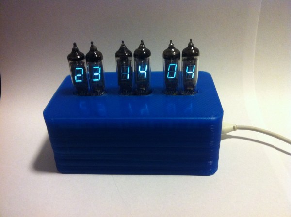
POV Clock Spins Light Filter Instead Of LEDs

This hard-drive based POV clock is a treasure trove of great design choices. Now, we’ve seen a bunch of spinning clock builds. Several of the hard drive versions use slits cut in the platters to create a display by illuminating an LED behind those slits at just the right moment. This is a similar idea but [Jason Hotchkiss] ditched the platters all together and replaced them with a light filter. The filter disc has digits 0-9 as well as a colon (not seen above because the colons blink each second). As this disc spins, the Arduino compatible controller lights up LEDs in the eight digital positions to illuminate the correct number.

The filter is made from an etched copper-clad disc. This is a great choice because the fiberglass substrate is strong, light weight, translucent, and available. The filter idea also means you don’t need to get power or data to a spinning platform. [Jason] has also designed a very impressive controller board that is the same size as the footprint of the laptop hard drive he’s using. Check out the video after the break to see his description of what went into the hardware choices he arrived upon. Continue reading “POV Clock Spins Light Filter Instead Of LEDs”

Very Accurate Clock Can’t Be Read Accurately

[Martijn] is showing off his new clock which he calls a Light Spectrum Clock. We like to look of it, using RGB LEDs in five squares that remind us of some of those LED coffee table builds. From left to right this shows the week, day, hour, minute, and second. Simple, right?

We had to smile a little bit when looking through his write up. He chose an Arduino nano as a controller, using a TLC5940 chip to drive the LEDs. But it is the inclusion of a DS1307 real-time clock that we find amusing. It will keep quite accurate time (not quite as well as the DS3232 but still respectable) but the fuzzy display technique makes telling the time accurately an impossibility. But like other color-based clocks, that’s part of the fun. The real reason for using an RTC chip is that they usually include battery-backed operation so that you can shut off the LEDs when you’re not around and the clock will continue to tick.

You can watch the seconds pass by as fading colors in the clip after the break.

Continue reading “Very Accurate Clock Can’t Be Read Accurately”

Tutorial: Build A Manifold Clock For $10

Every once in a while, the Hack a Day tip line gets a submission that is cool, but screams to be built in a few hours, possibly while consuming adult beverages. When [Shay] and [Ben] sent in their Manifold Clock Kickstarter, I knew what I had to do. To make a long story short, there’s a manifold clock hanging on my wall right now. Check out my manifold clock how-to guide after the break.

Continue reading “Tutorial: Build A Manifold Clock For $10”

Trashed Hard Drive? Why Not An Engraved Clock?

So your hard drive quit working.  Don’t despair, with a “little” work your disk can be repurposed into a clock like the one seen above. I made this clock after several iterations of various success, including the first revision, which was simply the platter with a clock kit from a hobby store screwed into the middle. Still a very neat effect, but if you want to actually tell what time it is, it helps to have the numbers available.

For this, you’ll need some sort of CNC machine (a kit-build router in this case), and some way to generate the Gcode to get everything cut correctly. A guide to how the logo was eventually turned into something a machine could understand is provided here. Of course if you’re not sure what logo would look good on your clock, you can always skip a few steps and engrave the our logo. In this [HAD] article, it’s conveniently provided in .dxf format, which can be converted by a CAM (computer-aided manufacturing) program into code that your machine can understand.

Check out after the break for a video of two “platter clocks” being engraved using these methods: Continue reading “Trashed Hard Drive? Why Not An Engraved Clock?”

Oscilloscope Clock Made Possible By Dumpster Diving

We see people driving around the night before trash collection and reclaiming items doomed to the land fill (or on their way to recycling… who knows). We’re beginning to think we need to join those ranks. Case in point is this vintage oscilloscope which [Bob Alexander] plucked from the curb in the nick of time. Here’s the kicker, when he got it home he found it still worked! He couldn’t let this opportunity go to waste, so he figured out how to turn it into a clock without losing the ability to use it as a scope.

You probably already know that it’s possible to display your own graphics on an oscilloscope. In fact, you can buy a board from Sparkfun which will turn the scope into an analog clock, and that’s exactly what [Bob] did. But he was met with two problems, the X-axis was flipped and he didn’t have an easy way to power the board.

He struggled with the voltage supply, frying his first attempt at boosting the internal 6.3V supply to use with a linear 5V regulator. His second attempt worked though, soldering a 12V regulator to the transformer. He was then on to the X-axis correction, using a rail-to-rail op-amp to invert the signal. The project finishes by adding toggle controls and buttons on the back of the case to switch between scope and clock modes, and to set the time.

[Jack]’s Solar-powered Clock

Hack A Day’s own [Jack Buffington] finally finished the solar clock he built for the buildlounge.com laser cutter giveaway.

[Jack] has been putting up the build log on his blog, and now the project is finally complete. The clock operates entirely on solar power. Instead of fancy-smanchy electronics, this clock puts a new spin on the very old school sundial. A box outside [Jack]’s house captures sunlight and focuses it onto an array of optical fibers. These fibers transmit the sunlight though the wall and to the face of the clock. Only a portion of the fibers are lit at any one time, and these correspond to the time of day. With a lot of confusing fiber routing, the clock can indicate the time of day by lighting up the clock face.

We covered the nascent beginnings of this project when it was still a glimmer in [Jack]’s eye, and we’ve got to hand it to him. This is a really creative project, and the addition of the ‘daylight savings time lever’ is the icing on the cake. Check out the video after the break for a great explanation of how the clock actually works, and be sure to check out the project on BuildLounge.

Continue reading “[Jack]’s Solar-powered Clock”

A Clock Made Out Of Some Very Weird Tubes

If you’re like [Richard], you’ve got a few really rare components lying around. Maybe it’s a very weird micro or a really tiny CRT, but eventually you’ve got to build something with these parts. When [Richard] decided to put some ITS1A neon display tubes to use, he fell back to the old standby – a really awesome clock.

Unlike the lowly Nixie tube, the ITS1A tube is weird. It’s a neon seven-segment display that can be controlled directly from the pins of a microcontroller. It does this with the help of seven tiny thyratrons in each segment. Even though this tube has neon, the display isn’t the familiar neon orange-red. The tube emits a lovely green with the help of a phosphor coating.

With a single digit already incorporated into [Richard]’s clock, he needed four indicators for the hours and minutes. After a failed experiment with a crazy 4-color, 16-pixel Melz ITM2-M display, he moved on to a simpler MTX90 thyratron indicator.

Using the same control scheme as his earlier numitron clock, Richard had a PCB made and wired everything up. The seven-segment tube indicates the value, and the indicator tubes indicates the position of the digit in the XX:XX standard. A very cool  build with parts you don’t see coming around often.