Before the invention of the high-powered LED, and even really before the widespread adoption of electric lights in general, lighthouses still had the obligation of warning ships of dangers while guiding them into various safe harbors. They did this with gas lights and impressive glass lenses known as Fresnel lenses which helped point all available light in the correct direction while reducing weight and material that would otherwise be used in a conventional lens.
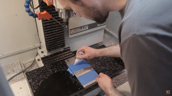
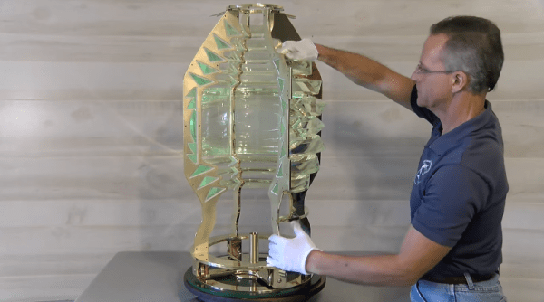
Now, a company in Florida is using acrylic in reproductions of antique Fresnel lenses. At first glance, it seems like acrylic might not be the best substitute for glass, but the company is able to achieve extreme precision using a CNC machine and then polishing and baking the acrylic which makes it transparent and excellent for use in lighthouse lenses like this. The reproduction lenses are built out of brass, and the lens elements are glued in place with a special adhesive. It’s a convincing replication worthy of use in any lighthouse.
Be sure to check out the video below to see how these lenses are built, and although we’re not entirely sure what exactly is being sprayed on the lenses when they are being polished, perhaps someone in the comments section can illuminate that for us. Of course, there are other uses for Fresnel lenses than in lighthouses, and we’ve seen some great examples of them put to use for many different applications.