Learning The Ins And Outs Of USB With A Simple Dev Board

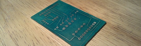
We can’t count the number of projects we’ve seen on Hackaday with a USB port.  Unfortunately, most of these builds – from RepRap controllers to wireless data loggers – don’t use the full capabilities offered to them with USB. [Ben] came up with a very cool USB breakout board that allows you to explore the USB protocol with just a single inexpensive ATtiny.

Instead of relying on an FTDI chip or otherwise sending serial data down a USB pipe, [Ben]’s project is meant to be the hardware compliment to his book on programming USB devices. His hardware board is exceedingly simple, just an ATtiny 2313, a USB port, and a handful of other components, but allows [Ben] to receive data on eight pins on a breadboard and send them over USB to a computer.

[Ben] had sent in his USB figure eight controller, a board that displays the numbers 0 through 9 according to what data is received via USB, a while ago. It’s a truly useless build aside from learning how USB works, but an excellent tool if you’d like to program your own USB device.

Generating Truly Random Sequences

Your brain can’t generate random numbers, and computers can’t either. Most of the ‘random’ numbers we come across in our lives are actually pseudorandom numbers; random enough for their purpose, but ordered enough to throw statistical analyses for a loop. [Giorgio] thought generating random sequences would make for an excellent project, so he whipped up a random sequence generator out of a few Opamps, resistors, and a handful of caps.

[Giorgio] used a Chua Circuit – a circuit that models nonlinear equations – to create a chaotic system. When pairs of points from these systems of equations are plotted on a graph, a fabulous and chaotic ‘double scroll’ pattern (seen above) can be found. After taking oscilloscope probes to different points on his Chua circuit, [Giorgio] watched chaos magically appear on his ‘oscope screen.

The double scroll pattern isn’t exactly random, but since the Z signal of his circuit chaotically varies between positive and negative, the only thing needed to create a random sequence of 1s and 0s is sending the Z signal through a comparator.

After calibrating and sampling his circuit [Giorgio] captured thousands of samples at a rate of 5 samples per second. From a cursory glance, it looks like [Giorgio]’s circuit is at least as good as flipping a coin, but proper tests for randomness require many more samples.

A very, very cool piece of work that is much, much more elegant than getting random bits from a Geiger counter.

Making A Gigantic 18 Pole 16 Throw Switch

When you’re building something that hasn’t been done before, sometimes the parts you need just don’t exist.

[Bacteria] over on the Made by Bacteria forum is building a huge all-in-one video game machine, combining hardware from 16 different consoles released through the years. This build requires a way to switch the video output between consoles, so [Bacteria] made a gigantic 18 pole 16 throw switch.

The build began with [Bacteria] sourcing a few 8-pole switches. Of course this switch was too small to toggle between the 16 output lines for each system, so these switches were doubled up and activated by a single button. This system worked, but the results weren’t ideal.

[Bacteria] gave in to the temptation of building his own switch by using spring-loaded metal nuts as the contacts for each part of the switch, allowing him to switch between consoles with a simple sliding contact.

So far, it looks like [Bacteria]’s Project Unity is shaping up nicely. We’ve seen a bit of the controller portion of [Bac]’s build, and already it’s shaping up to be a wonder of retro gaming.

You can check out [Bacteria]’s breakdown of his switch after the break and his Instructable here.

Continue reading “Making A Gigantic 18 Pole 16 Throw Switch”

Prototyping With Very, Very Small ICs

Gone are the days when all the cool chips are able to be thrown into a breadboard very easily. [starlino] was working with a circuit that uses an accelerometer, but unfortunately these chips come in hard to solder LGA-16 packages. [starlino] figured out a way to prototype with these packages that doesn’t require a custom breakout board or spending any time watching a reflow oven.

[starlino]’s LGA-16 adapter board began with a piece of perf board drilled out to form a space that perfectly fits his accelerometer. A piece of tape is placed over the pads of the chip and perf board, and the gap between the chip and board is filled in with a two-part plumbers putty.

Once the putty has cured, the leads on the acclerometer are connected to the pads on the board with a silver conductive pen. After putting a few header pins in the corners of the board, [starlino] soldered the pads to the pins and had a permanent breakout board for a very small accelerometer.

It’s not by any means a pretty build, but after [starlino] sealed the entire build in liquid electrical tape and installed it in a DIP socket, he had a completely functional accelerometer in an easy to prototype package. Not bad for a breakout board that can be built from stuff just lying around a workbench.

Buying Cheaper Electronics And Not Saving Money

As an engineer at Spectrum Design in Minneapolis, [Carl] works with clients to get their product out to the masses. When designing a new USB-powered device, one client thought it would be a great idea to include a USB car charger with the device. The client promptly ordered a few thousand car chargers from China and everything was going swimmingly.

Everything was fine, of course, until [Carl] decided to test the Chinese car chargers with the client’s device. The USB PHY burnt out in short order, and the likely culprit was a shorted 12 volt regulator. This demanded a closer inspection, so after cracking open the charger [Carl] was amazed at what he found.

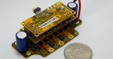
Yes, what you see on that circuit board is accurate. The manufacturer of these car chargers never even populated the switched mode regulator for this car USB charger.  Amazing, considering a single 10 cent 7805 DC regulator would have almost worked for this application.

If there was ever an example of being careful when purchasing the cheapest possible product to increase profit margins, this would be it.

Ever the engineer, [Carl] sent this into the tip line as a Word document. That’s available here, along with a slide show of the pictures [Carl] snapped.

Continue reading “Buying Cheaper Electronics And Not Saving Money”

Southwest Tour: Scrap Tattoo Gun

I had an idea for keeping things interesting on this long road trip through the southwest. I was going to gather a few bits from each hackerspace and build something using minimal tools while we were driving down the road.  I settled on the idea of a really simple “jailhouse” tattoo gun. I knew I could build one from parts I could source very easily and that I wouldn’t need much in terms of tools to make it happen.

Continue reading “Southwest Tour: Scrap Tattoo Gun”

Taking A Look At Decapped ICs

Aside from wanting to play around with nitric acid, [Ben] really didn’t have a reason to decap a few 74xx and 4000-series logic chips. Not that we mind, as he provides a great tutorial at looking at a bare IC that isn’t covered in epoxy and resin.

Most ICs are encased in a hard epoxy shell making it very difficult to look at the circuits within. [Ben] tried to grind this epoxy off with a Dremel tool, but didn’t have much luck until he moved over to a CNC mill to remove 0.040 – 0.050″ of epoxy without breaking the bond wires.

After carving out a nice pocket above the die, [Ben] put a few drops of nitric acid on the chip to dissolve the epoxy coating.  This worked very slowly at room temperature, but after putting the chips on a hot plate the acid was able to reveal the die underneath.

After successfully removing all the epoxy and giving them an acetone bath, [Ben] took his chips over to the microscope and was able to check out the underlying circuit. He doesn’t have any idea what he could do with these decapped logic chips, but the bond wires are still intact so he could still use these chips in a build.

We’d like to see a few decapped MEMS devices, but if you have a suggestion on what [Ben] can do with his decapped chips, drop a note in the comments.

Continue reading “Taking A Look At Decapped ICs”