Drawing Things Very Slowly, Very Easily

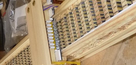
A while back, we saw [Euphy]’s polar pen plotter project. The mechanics of the build are very simple – just a pair of motors attached to a pen by a beaded cord. Even though the build is very simple, it’s possible to create awesome works of art albeit very slowly.

Since we featured [Euphy]’s polar pen plotter, a lot of improvements have been made. Now the Polargraph has an SD card slot for computer-less printing, a touch screen for manual control of the plotter, and a few new drawing styles that improve on the previous version a lot.

Right now the improved version of the Polargraph is set up in the front of a graffiti art supply shop in Edinburgh where it spends its time slowly drawing a window dressing. [Euphy] put up a few videos of what the Polargraph is capable of doing, very impressive and we hope he gets a few more PCBs in soon.

Continue reading “Drawing Things Very Slowly, Very Easily”

Hackathon Results In The Facebook Book

[Jeremy Blum] and [Jason Wright] pose with their project at the end of a 24 hour hackathon. The Facebook headquarters in New York City held the event as part of their Summer of Hack program. As an homage to the hosts, the hacking duo decided to create a physical book and populate it with the virtual Facebook. And what do you call such a creation? The Face(book)^2.

The video after the break gives the best overview of the hardware, but here’s the gist of it: They started with the largest hardcover book they could find, hollowing out its pages to house their own hardware. When you open the book it calls back to a computer over an Xbee link with a request for data. The python script on the computer pulls the newest from a Facebook feed, sending it back to the book to be displayed. There is a graphic LCD and four character LCDs built in for this purpose. There’s also an accelerometer which is used for detecting page turns when the cover is jostled. The rest of the interactivity is provided by a few tactile switches mounted next to the smaller LCD screens for navigation and the ‘like’ feature.

Continue reading “Hackathon Results In The Facebook Book”

Mechanical Relay Logic That Was Snubbed For A Microcontroller

[Alex] was tasked with a control design problem for a set of motors. The application called for the back of a truck to open up, some 3D scanning equipment to rise from its enclosure, and finally the equipment needed to rotate into place. All of this needed to happen with one flip of a switch, then proceed in reverse when the switch was turned off. We can understand why the final design used a microcontroller, but we also think that [Alex’s] relay logic circuit is an eloquent way of doing things.

He uses limiting switches as the feedback loop for the logic. In the video after the break he walks us through the schematic. Each of the three motors has an up and down limiting switch. These control the three relays which switch power to the motors. We like the design because interrupting the movement mid-operation provides no problem for the system. The only real issue we see is that relays wear out, and the automotive application of the hardware may cause this to happen more quickly than normal.

You may recognize the clear gears used in the demo. [Alex] previously showed us how he makes those.

Continue reading “Mechanical Relay Logic That Was Snubbed For A Microcontroller”

Geigers On A Plane

[Thomas] took a Geiger counter he built on a plane. Why? Because he can, much to the chagrin of airport security.

[Thomas]’ Geiger counter is built around an old Russian SBT-10A detector containing ten separate Geiger tubes. This tube was connected to a circuit containing a LiPo battery, a few high-voltage components, and an audio jack connected to the tubes themselves. When alpha, beta, or gamma radiation hits one of the Geiger tubes, an enormous click is sent to the audio jack and into the microphone jack of a small netbook.

Right after boarding a plane in Dublin, [Thomas] booted up his computer, started recording in Audacity, plugged in his Geiger counter, and stored his experiment safely in the overhead compartment. After landing in Prague a few hours later, [Thomas] saved the 247 MB .WAV file and began working on a way to convert clicks in an audio track into usable data.

The audio output on the Geiger counter overloaded the mic input on his netbook, making ‘event detection’ very easy with a small C app. After plotting all the data (seen above), [Thomas] had a complete record of the radiation on his 2-hour flight.

Because there was far less atmosphere to absorb cosmic radiation, [Thomas]’ radiation dose was 9.1 microsieverts. Much more than at sea level, but nothing even air crews need to worry about.

Emulating The DCPU On An AVR

[skywodd] just finished his own DCPU emulator (French, translation) based on [notch]’s upcoming game, 0x10c. The neat thing about [skywodd]’s build is his emulator uses the lowly ATMega328, the same microcontroller found in (some) Arduinos.

The DCPU specification goes over the operations required of any DCPU emulator. There’s a lot of crazy stuff here – a division instruction that takes only 3 clock cycles, using an overflow for carry conditions, and a complete lack of a JMP instruction – but [skywodd] was able to tease something apart from DCPU studio and a VGA interface

Everything in this emulator is built on a solderless breadboard, but the ROM and RAM isn’t complete yet. As of now, everything is handled by the ‘328, using 478 bytes of RAM on the microprocessor.

We promised we would be holding a contest for the best physical implementation of the DCPU when we caught wind of 0x10c, and [skywodd]’s build is starting to look like the beginnings of the winning entry. We honestly have no idea when we’ll be holding this contest, but it’ll probably be shortly after the first playable release. Go bug [notch] if you’d like to speed up the progress, because obviously Twitter abuse speeds up software development.

How’s The 60Hz Coming From Your Wall?

If you’ve ever wondered why NTSC video is 30 frames and 60 fields a second, it’s because the earliest televisions didn’t have fancy crystal oscillators. The refresh rate of these TVs was controlled by the frequency of the power coming out of the wall. This is the same reason the PAL video standard exists for countries with 50Hz mains power, and considering how inexpensive this method of controlling circuits was the trend continued and was used in clocks as late as the 1980s. [Ch00f] wondered how accurate this 60Hz AC was, so he designed a little test.

Earlier this summer, [Ch00f] bought a 194 discrete transistor clock kit and did an amazing job tearing apart the circuit figuring out how the clock keeps time. Needing a way to graph the frequency of his mains power, [Ch00f] took a small transformer and an LM311 comparator. to out put a 60Hz signal a microcontroller can read.

This circuit was attached to a breadboard containing two microcontrollers, one to keep time with a crystal oscillator, the other to send frequency data over a serial connection to a computer. After a day of collecting data, [Ch00f] had an awesome graph (seen above) documenting how fast or slow the mains frequency was over the course of 24 hours.

The results show the 60Hz coming out of your wall isn’t extremely accurate; if you’re using mains power to calibrate a clock it may lose or gain a few seconds every day. This has to do with the load the power companies see explaining why changes in frequency are much more rapid during the day when load is high.

In the end, all these changes in the frequency of your wall power cancel out. The power companies do the same thing [Ch00f] did and make sure mains power is 60Hz over the long-term, allowing mains-controlled clocks to keep accurate time.

Servos, Servos, And More Servos

For one reason or another, a lot of Hackaday readers are doing stuff with servos as of late. Here’s a few servo hacks that made their way into our tip line over the past day or so:

USB servo controller and a Stewart Platform

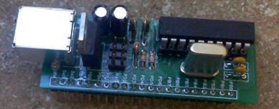
[Patricio] needed a way to control a bunch of servos for his thesis project. He came up with a USB servo controller (Spanish, here’s the translation) powered by a 40-pin PIC 18F microcontroller. The board connects to the USB port of a computer and supports up to 8 servos with 8 additional digital I/Os. Why all this horsepower? It’s for a Stewart Platform [Patricio] and his partner [Natalia] built.

Continuous rotation servos

Standard servos are usually limited to a rotation angle of somewhere between 140 and 160 degrees. Sometimes you need a continuous rotation servo, and those are a little more expensive. Every servo is a continuous rotation servo if you disable a the variable resistor as [Valentin] shows us. It’s a simple, if old, hack. It’s new to someone, though.

Eight servos on a Raspi

[Mikael] made a little board to attach to the GPIO header of his Raspberry Pi and control up to 8 servos. The board is running a serial interface with a small microcontroller on board. There’s nothing in the way of schematics or code, a testament for why you should always use a good email address when sending something into the HaD tip line. It seems [Mikael] is making a proper board, and we’ll more than happily give it a full post when it’s complete.