Potting Electronics With Silicone

If you want to improve the reliability of your electronics, just cover them in silicone or epoxy. Potting, as this technique is called, protects your project from impact and loose wires, but most of the time ends up as a gloppy mess. [Charles] figured out an awesome way to make pro-looking potted electronics using silicone and a few supplies from the emergency room.

On one of [Charles]’s trips to the ER, a nurse put Tegaderm on a wound and he noticed his skin could breathe. Figuring Tegaderm would also allow silicone to breathe, he asked for a sample and went back to the lab. After putting a few globs of silicone on a PCB, [Charles] wrapped the whole thing in Tegaderm. Much to his surprise, the silicone cured and made a smooth, glossy protective covering on his board.

[Charles] put up a Picassa album of his Tegaderm/silicone potted electronics, and we’ve got to say they’re looking very professional. This technique could also be applied to [Charles]’ glass PCB touch sensor, allowing for the creation of clear (or at least tranlucent) PCBs.

After the break, you can check out [Charles] potting his ATtinyISP board in silicone with Tegaderm. One word of warning, though: don’t use a silicone that uses acetic acid to cure – that’s a death sentence to electronics. Luckily, there’s an easy test to see if your particular brand of silicone produces acetic acid while curing. Just squeeze a bit of silicone on a piece of scrap, and if it smells like vinegar after a while, don’t use it.

Continue reading “Potting Electronics With Silicone”

GPU Programming For Easy & Fast Image Processing

If you ever need to manipulate images really fast, or just want to make some pretty fractals, [Reuben] has just what you need. He developed a neat command line tool to send code to a graphics card and generate images using pixel shaders. Opposed to making these images with a CPU, a GPU processes every pixel in parallel, making image processing much faster.

All the GPU coding is done by writing a bit of code in GLSL. [Reuben]’s command line utility takes that code, sends it to the graphics card, and returns the image calculated by the GPU. It’s very simple for to make pretty Mandebrolt set images and sine wave interference this way, but [Reuben]’s project can do much more than that. By sending an image to the GPU and performing a few operations, [Reuben] can do very fast edge detection and other algorithmic processing on pre-existing images.

So far, [Reuben] has tested his software with a few NVIDIA graphics cards under Windows and Linux, although it should work with any graphics card with pixel shaders.

Although [Reuben] is sending code to his GPU, it’s not quite on the level of the NVIDIA CUDA parallel computing platform; [Reuben] is only working with images. Cleverly written software could get around that, though. Still, even if [Reuben]’s project is only used for image processing, it’s still much faster than any CPU-bound method.

You can grab a copy of [Reuben]’s work over on GitHub.

APC Android Computer Isn’t A Raspberry Pi

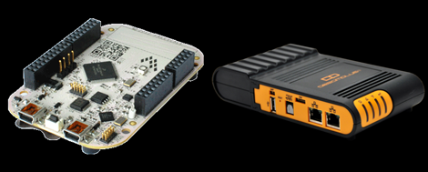
VIA Technologies, ostensibly in an attempt to compete with the Raspberry Pi (if you can believe all those bloggers out there), is releasing a tiny single board computer called the APC Android PC. The VIA website for the APC is down, so just search Google News for all the details.

The specs are somewhat similar to the Raspberry Pi – HDMI out, Ethernet, SD card, and a few USB ports – but that’s about where the similarities end. The APC runs a version of Android 2.3 customized for mouse and keyboard input where the RasPi runs Linux. The APC can only display 720p video (compared to the RasPi’s 1080p), and doesn’t have GPIO pins that can be used with Arduino shields.

We’re pretty sure VIA is going after the media center PC market here with a low-power board that can easily stream movies or a season of TV shows over a network. At $50, we’re sure the APC will find a home in a few homebrew devices, MAME machines, and carputers.

If anything, this only portends a whole bunch of single-board ARM/Linux computers riding on the coat tails of the RasPi. That’s awesome no matter how you look at it.

If a $50 Android board doesn’t whet your whistle, VIA also released a Mini-ITX board with 12 hardware serial ports. Hardware serial ports are getting rare nowadays despite how useful they are for embedded applications. 12 (with riser cards, natch) serial ports seems overkill, but we’re sure some Hackaday reader has been looking for this board for a while now.

Viper Flight Simulator (a La Battlestar Galactica) Finished

Here’s a story about some guys who set out to build a flight simulator for the Viper from Battlestar Galactica. The goal is to bring a grand project to the Maker Faire. This is a recurring challenge for the group, which has participated over the last several years. But this year they decided to go big and mounted a successful Kickstarter campaign to help with the cost.

The best place to get the build details is their progress updates page. Each week the cadre of teenagers tried to post some info about their progress, and we’ve got a big grin on our faces after reading through them. The simulator aims to provide you with as much of a space flight experience possible given the restraints which gravity imposes. The cockpit can roll and pitch a full 360 degrees in each direction. Of course safety is a concern and they were careful with their frame design and pilot restraint system. But so much more goes into this than just the physical build. There’s sound, lighting, and the virtual simulator, all of which have been complete at an impressive quality level. There’s a ton of video posted and we’ve embedded one short clip after the break showing off the cockpit’s dashboard.

Continue reading “Viper Flight Simulator (a La Battlestar Galactica) Finished”

Getting Great Bootlegs With The BootlegMIC

Go to any concert, show, or basement band practice, and you’ll find someone recording a bootleg. While these live recordings are sometimes fairly high quality, bootlegs recorded with a cell phone usually sound terrible. The guys over at Open Music Labs have a great solution to these poor quality recordings that only needs a few dollars worth of parts.

The project is called bootlegMIC. It’s a simple modification of an electret microphone – the same type of mic found in cellphones and bluetooth headsets – that allows for some very high quality recording in very noisy environments. According to the open music labs wiki, the modification is as simple as cutting a few traces on the PCB in an electret mic and soldering on a cap and a few resistors.

An electret mic contains a small JFET to amplify the signal coming from the microphone diaphragm; the specific JFET is selected by the manufacturer to ensure the microphone has the right gain and response. Usually these JFETs are chosen with the expectation of a relatively quiet environment, and trying to record a concert only results in a ton of distortion. By putting a resistor between the source of the JFET and ground of the microphone, it’s possible to reduce this distortion.

The circuit is easy enough to solder deadbug style, and should work with most cellphones. The guys at Open Music Lab were able to get their mic working with an iPhone, but they’re still working on figuring out the Android mic input. There’s a great demo video showing the improvement in audio quality; you can check that out after the break.

Continue reading “Getting Great Bootlegs With The BootlegMIC”

IPhone Charger Teardown Shows Astounding Miniaturization.

There’s no question that Apple has their industrial design down pat; comparing a cell phone charger made by Blackberry or Motorola to the tiny 1-inch-cube Apple charger just underscores this fact. [Ken Shirriff] posted a great teardown of the Apple iPhone charger that goes through the hardware that makes this charger so impressive.

Like most cell phone chargers and power supplies these days, Apple’s charger is a switching power supply giving it a much better efficiency than a simple ‘transformer, rectifier, regulator’ linear power supply. Inside the charger, mains power is converted to DC, chopped up by a control IC, fed into a flyback transformer and converted into AC, and finally changed back into DC, and finally filtered and sent out through a USB port.

The quality of the charger is apparent; there’s really no way this small 1-inch cube could be made any smaller. In fact, if it weren’t for the microscopic 0402 SMD components, it’s doubtful this charger could be made at all.

Comparing the $30 iPhone charger of a cheap (and fake) iPhone charger, the budget charger still uses a flyback transformer but there are serious compromises of the safety and quality. The fake charger doesn’t use a power supply controller IC and replaces the four bridge diodes for a single diode to rectify the AC; a very efficient cost-cutting measure, but it does lead to a noisier power supply.

There’s also the issue of safety; on the Apple charger, there is a (relatively) huge physical separation of  ~340 VDC and your phone. With the off-brand charger, these circuits are separated by less than a millimeter – not very safe, and certainly wouldn’t be UL approved.

It’s worth pointing out that [Ken] compares a similar $7 Samsung charger favorably to the $30 Apple charger. Both are functionally identical, but Apple also has their  marketing down pat, to say the least.

Tip ‘o the hat to [George] for sending this in.

EDIT: In case a 1-inch cube wasn’t impressive enough, check out the euro version of the iPhone/iPad charger. It supplies 1A @ 5V, and isn’t much thicker than the USB port itself. Thanks [Andreas] for bringing this to our attention. If anyone wants to do a teardown of the euro version, send it in on the tip line.

Printing Circuitry On A RepRap

Over on the RepRap blog, [Rhys] has been experimenting with molten metal to build circuits with the RepRap.

Last June, [Rhys] found a neat alloy made of Tin, Bismuth, and a little bit of Indium that melts at around 130° C, and has just the right properties to be extruded with a standard RepRap setup. The results were encouraging, but the molten metal quickly dissolved the brass and aluminum nozzles [Rhys] was pushing liquid metal through.

The solution to this problem was solved by anodizing the heck out of a RepRap nozzle to make a hard, protective oxide layer. Already [Rhys] has logged hundreds of hours squirting molten metal out of his RepRap with no signs of any damage to the nozzle.

Since [Rhys] figured out how to print in metal, he whipped up an extremely minimal Sanguino board. You can see this RepRapped PCB running a LED blink program after the break. Now to work on the RepRap pick and place…

Continue reading “Printing Circuitry On A RepRap”