What do you get when you take a massive number of LEDs and combine them with a shopping cart and a bicycle? An awesome rave-mobile created by [kramerr]. He’s even taking it one step further by making the electronics solar powered.
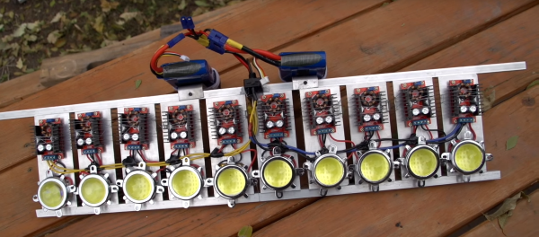
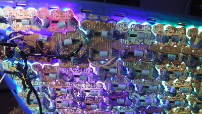
[Kramerr] controls the LEDs with multiple WS2803 LED drivers. Three PIC18F4550s control the WS2803s over SPI. He devised a neat way of exciting the LEDs from music by using a pair of graphic equalizer display filter chips, MSGEQ7s, to drive the PICs to create patterns. A USB input also allows the PICs to display song titles or other information.
The mechanical design is as impressive as the electronics. The rear half of a bicycle is welded to the frame of the shopping cart with the cart’s handle used for steering. The shopping cart’s rear wheels are replaced by small bicycle wheels.
But [Kramerr] wasn’t done. He built his own solar panel since he couldn’t find one to fit the size requirements. The panel consists of 26 cells connected in series to provide 1A at 13V on a sunny day. A solar charge controller keeps a standard 12v lead acid battery ready to power the tricycle cart.
And there is still more! There is a sound system driven by a Raspberry Pi. The Pi also drives the USB inputs when [Krameer] wants to display song titles or artists instead of the audio patterns.
There are at least four hacks in this project each worthy of applause. [Karmeer] deserves an ovation for doing all of them in one project. If you are looking for less bling and less pedaling may we direct you to this powered, riding shopping cart.
Some rave music and lights via video after the break.
Continue reading “A Sound And LED-tastic Tricycle Shopping Cart”