[GreatScott!] was bummed to see his greenhouse be empty and lifeless in winter. So, he set out to take the greenhouse home with him. Well, at least, a small part of it. First, he decided to produce artificial sunlight, setting up a simple initial experiment for playing with different wavelength LEDs. How much can LEDs affect plant growth, really? This is the research direction that Würth Elektronik, supporting his project, has recently been expanding into. They’ve been working on extensive application notes, explaining the biological aspects of it for us — a treasure trove of resources available at no cost, that hackers can and should learn from.
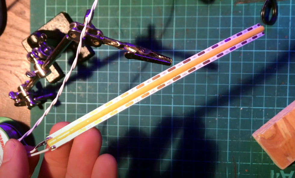
Initially, [GreatScott!] obtained LEDs in four different colors – red, ‘hyper red’, deep blue, and daylight spectrum. The first three are valued because their specific wavelengths are absorbed well by plants. The use of daylight LEDs though has been controversial. Nevertheless, he points out that the plant might require different wavelengths for things other than photosynthesis, and the daylight LEDs sure do help assess the plants visually as the experiment goes on.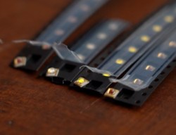
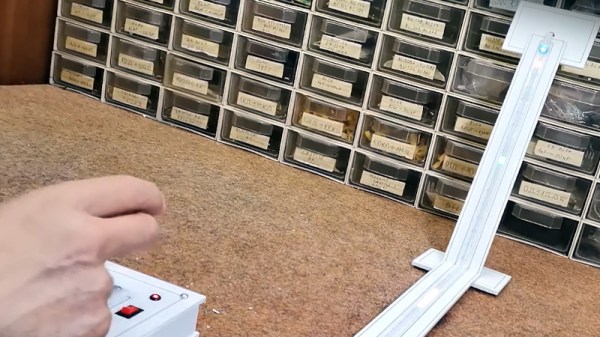
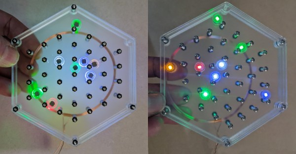
Next, [GreatScott!] borrowed parts of Würth’s LED driver designs, creating an Arduino PWM driver with simple potentiometers. He used this to develop his own board to host the LEDs.
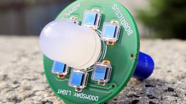
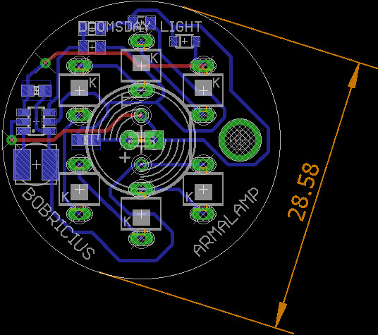
An aluminum PCB increases heat dissipation, prolonging the LEDs lifespan. [GreatScott!] reflowed the LEDs onto it with solder paste, only to find that the ‘hyper red’ LEDs died during the process. Thankfully, by the time this problem reared its head, he managed to obtain the official horticulture devkit, with an LED panel ready to go.
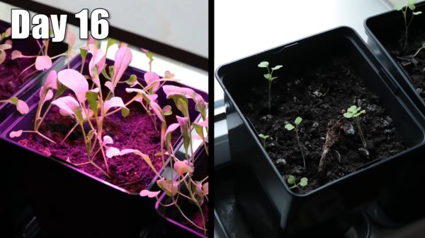
[GreatScott!’s] test subjects were Arugula plants, whose leaves you often find on prosciutto pizza. Having built a setup with two different sets of flower pots, one LED-adorned and one LED-less, he put both of them on his windowsill. The plants were equally exposed to sunlight and equally watered. The LED duty cycle was set to ballpark values.
The results were staggering, as you can see in the picture above — no variable changing except the LEDs being used. This experiment, even including a taste test with a pizza as a test substrate, was a huge success, and [GreatScott!] recommends that we hit Würth up for free samples as we embark on our own plant growth improvement journeys.
Horticulture (aka plant growing) is one of the areas where hackers, armed with troves of freely available knowledge, can make big strides — and we’re not even talking about the kind of plants our commenters are sure to mention. The field of plant growth is literally fruitful and ripe for the picking. You can accomplish a whole lot of change with surprisingly little effort. The value of the plants on your windowsill doesn’t have to be purely decorative, and a small desk-top setup you hack together, can easily scale up! Some hackers understand that, and we’ve started seeing automated growing solutions way before Raspberry Pi was even a thing. The best part is, that you only need a few LEDs to start.
Continue reading “Plant Growth Accelerated Tremendously With LEDs” →