Lego Heist Bot Steals Keys

Breaking and entering is a felony offense, and one that risks the interloper receiving serious bodily harm for the trouble. Sending in a robot instead is an attractive alternative. While we doubt any actual intention to use their creation for evil, [Brick Experiment Channel] have nonetheless built a viable heist bot out of Lego.

The robot in question is actually two, that work together to execute their mission. Once lowered in the house, the scissor lift bot drives into position next to a coffee table. It then lifts its companion bot into position by extending its motor-driven linear actuators. The recovery bot then drives out onto the table, snatches a set of keys with its arm, and returns to the lift bot, before exiting the house. It’s all achieved with the use of the SBrick, a third-party Lego accessory which allows remote control of Lego motors over Bluetooth. A wireless camera also helps out with vision for the platform.

Lego really does make it easy to build quick, functional mechanisms without a whole lot of fuss. We’ve seen it employed in all sorts of ways, like this handy film scanner. Video after the break.

Continue reading “Lego Heist Bot Steals Keys”

South Korea Blankets Country With Free WiFi On All Public Transit

Wrapping up a multi-year project to provide free WiFi on all public transportation, South Korea’s Ministry of Science and Information and Communications Technology (MSIT) announced that a total of 35,006 buses had been equipped nationwide.

Previously, subscriber-based WiFi had been installed on subways and in subway stations. It was provided privately by two phone carriers and free only for their subscribers. The coverage was spotty and slow, and in 2017 the government took over and implemented a better system. With this announcement, the whole public transportation system is now covered with stable and free WiFi.

We also noticed that the government has released the details of the 220,000 WiFi access points to the public. This includes the location, IP address, and RSSI data for use by people and companies wanting to develop location-based services. What is the state of free WiFi access points in your region, and does it extend to public transportation? Do you find it reliable, or do you use your data plan when out and about?

Industrial Stack Light Keeps An Eye On Prusa Mini

When most people want to keep tabs on what their 3D printer is up to while they’re out and about, they’ll install OctoPrint on a Pi and be done with it. But what if you’re just on the other side of the room? Inspired by the stack lights used on factory floors, [Jeff Glass] decided to add a similar system to his Prusa Mini so he could see what it’s up to at a glance.

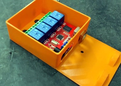
It turns out you can get these lights pretty cheaply online from the usual retailers, and as [Jeff] explains in the video after the break, driving them is about as easy as it gets. Rather than being some kind of addressable device, they generally have a single common 12 or 24 volt DC wire and ground lines for each color. With a USB controlled relay board, kicking on the appropriate light is simple from your operating system of choice.

What ended up being a bit harder was finding out what the Prusa Mini was up to. The printer offers up a simple status web page, but it has a few oddball quirks that make it difficult to scrape; such as presenting a little pop-up message that you have to manually close each time you load the page. But after spending some time with the powerful Selenium library for Python, he was able to create a script that worked its way through the UI and pulled the relevant status messages. Obviously the resulting code is Prusa specific, but the general concept would work on other printers assuming you can find a reliable way to pull the device’s current status.

After coming up with a wall mounted enclosure for the electronics that doubles as a mount for the light itself, [Jeff] can now see if his printer needs attention from clear across the room. An especially nice feature when the printer is all buttoned up inside of its enclosure.

Continue reading “Industrial Stack Light Keeps An Eye On Prusa Mini”

Six Degrees Of Freedom Omnicopter With Ardupilot

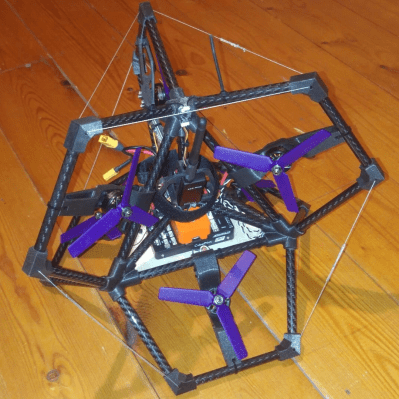
Modern multirotors are very maneuverable but are mostly limited to hovering in a single orientation. [Peter Hall] has gotten around this by building an omnicopter drone with six motors mounted in different orientations on a collapsed tetrahedron frame.

The shape of the frame consists of six tetrahedrons all joined together at a single point. With a motor in each frame, the drone can produce a thrust vector in any direction, to achieve six degrees of freedom. The control system is the challenging part of this project, but fortunately [Peter] is one of the Ardupilot developers. Unlike a standard multirotor, it doesn’t need to tilt to move around laterally but can keep its orientation constant. One of the limiting factors is that the motors need to stop and reverse rotation for direction changes, which takes time. At slow maneuvering speeds this isn’t a major problem, but at higher speeds rotation is noticeably less smooth.

Because the drone is symmetrical all around, keeping track of orientation is challenging for a human pilot, but it’s perfect for an autopilot system like Ardupilot. In the video after the break, [Peter] demonstrates this by flying the drone around while the autopilot rotates it randomly. The 6DoF control system is open source and a pull request is live to integrate it into the official version of Ardupilot. The obvious application for this sort of drone is for inspection in and around structures.

This omnicopter is an entry into the Lynchpin drone competition by the celebrity [Terrence Howard]. We’re not quite following his claims regarding the scientific significance of this shape, which he named the “Lynchpin”, but it works for drones. Continue reading “Six Degrees Of Freedom Omnicopter With Ardupilot”

AVR Microcontroller Doubles Up As A Switching Regulator

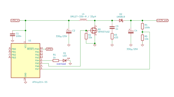
[SM6VFZ] designed, built and tested a switched-mode DC-DC boost regulator using the core independent peripherals (CIP) of an ATtiny214 micro-controller as a proof of concept, and it looks pretty promising!

A Buck, Boost, or Buck-Boost switching regulator topology usually consists of a diode, a switching element (MOSFET) and an energy storage device (inductor/capacitor) in the power path, and a controller that can measure the output voltage, control the switching element and add safety features such as current limiting and temperature shutdown. A search for switching regulators or controllers throws up thousands of parts, and it’s possible to select one specifically well suited for any desired application. Even so, the ability to use the micro-controller itself as the regulator can have several use cases. Such an implementation allows for a software configurable switch-mode regulator and easy topology changes (boost, buck, fly back etc.).
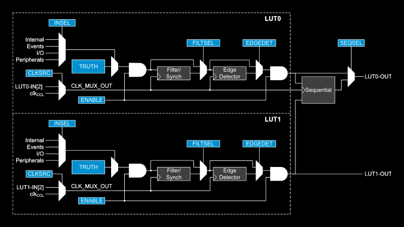
The “Getting Started with Core Independent Peripherals on AVR®” application note is a good place to get an overview of how the CIP functionality works. Configurable Custom Logic (CCL) is among one of the powerful CIP peripherals. Think of CCL as a rudimentary CPLD — a programmable logic peripheral, which can be connected to a wide range of internal and external inputs such as device pins, events, or other internal peripherals. The CCL can serve as “glue logic” between the device peripherals and external devices. The CCL peripheral offers two LookUp Tables (LUT). Each LUT consists of three inputs, a truth table, a synchronizer, a filter, and an edge detector. Each LUT can generate an output as a user programmable logic expression with three inputs and any device that have CCL peripherals will have a minimum of two LUTs available.
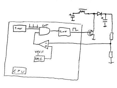
This napkinCAD sketch shows how [SM6VFZ] implemented the boost regulator in the ATtiny214. The AND gate is formed using one of the CCL LUT’s. The first “timer 1” on the left, connected to one input of the AND gate, is free running and set at 33 kHz. The analog comparator compares the boosted output voltage against an internally generated reference voltage derived from the DAC. The output of the comparator then “gates” timer 1 signal to trigger the second “timer 2” — which is a mono-shot timer set to max out at 15 us. This makes sure there is enough time left for the inductor to completely release its energy before the next cycle starts. You can check out the code that [SM6VFZ] used to built this prototype, and his generous amounts of commenting makes it easy to figure out how it works.

Based on this design, the prototype that he built delivers 12 V at about 200 mA with an 85% efficiency, which compares pretty well against regular switching regulators. Keep in mind that this is more of a proof-of-concept (that actually works), and there is a lot of scope for improvement in terms of noise, efficiency and other parameters, so everyone’s comments are welcome.

In an earlier blog post, we looked at how ATmegas with Programmable Logic came about with this feature that is usually found in PIC micro-controllers, thanks to Microchip’s acquisition of Atmel a few years back. But we haven’t seen any practical example of the CCL peripheral in an Atmel chip up until now.

The Shell And The Microcontroller

One of the nicest amenities of interpreted programming languages is that you can test out the code that you’re developing in a shell, one line at a time, and see the results instantly. No matter how quickly your write-compile-flash cycle has gotten on the microcontroller of your choice, it’s still less fun than writing blink_led() and having it do so right then and there. Why don’t we have that experience yet?

If you’ve used any modern scripting language on your big computer, it comes with a shell, a read-eval-print loop (REPL) in which you can interactively try out your code just about as fast as you can type it. It’s great for interactive or exploratory programming, and it’s great for newbies who can test and learn things step by step. A good REPL lets you test out your ideas line by line, essentially running a little test of your code every time you hit enter.

This is your development environment

The obvious tradeoff for ease of development is speed. Compiled languages are almost always faster, and this is especially relevant in the constrained world of microcontrollers. Or maybe it used to be. I learned to program in an interpreted language — BASIC — on computers that were not much more powerful than a $5 microcontroller these days, and there’s a BASIC for most every micro out there. I write in Forth, which is faster and less resource intensive than BASIC, and has a very comprehensive REPL, but is admittedly an acquired taste. MicroPython has been ported over to a number of micros, and is probably a lot more familiar.

But still, developing MicroPython for your microcontroller isn’t developing on your microcontroller, and if you follow any of the guides out there, you’ll end up editing a file on your computer, uploading it to the microcontroller, and running it from within the REPL. This creates a flow that’s just about as awkward as the write-compile-flash cycle of C.

What’s missing? A good editor (or IDE?) running on the microcontroller that would let you do both your exploratory coding and record its history into a more permanent form. Imagine, for instance, a web-based MicroPython IDE served off of an ESP32, which provided both a shell for experiments and a way to copy the line you just typed into the shell into the file you’re working on. We’re very close to this being a viable idea, and it would reduce the introductory hurdles for newbies to almost nothing, while letting experienced programmers play.

Or has someone done this already? Why isn’t an interpreted introduction to microcontrollers the standard?

New Part Day: Espressif ESP32-S3

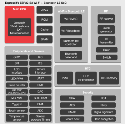
Since Espressif Systems arrived in our collective consciousness they have expanded their range from the ESP8266 to the ESP32, and going beyond the original WROOM and WROVER modules to a range of further ESP32 products. There’s a single-core variant and one that packs a RISC-V core in place of the Tensilica one, and now they’ve revealed their latest product. The ESP32-S3 takes the ESP to a new level, packing as it does more I/O, onboard USB, and an updated version of the two Tensilica cores alongside Bluetooth version 5. It’s still an ESP32, but one that’s more useful, and it’s worth a closer look because we expect it to figure in quite a few projects.

Espressif's block diagram for the chip.
Espressif’s block diagram for the chip.

Sadly the data sheet does not seem to have been released, but we do have some tidbits to consider. Espressif are anxious to tell us about its “AIOT” capabilities thanks to the vector instructions in the EXTensa LX7 cores (PDF) that were not present in the previous model’s LX6. They claim that this will speed up software neural networks; this does have an air of marketing about it but we’ll withhold judgement until we see it in use. The new core certainly will offer a performance improvement across the board though, which should be of interest to all ESP32 developers. Meanwhile the ultra-low-power core that existing ESP32 developers will be familiar with remains.

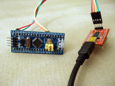
Then there is that USB support, which appears in the feature block diagram but has little information elsewhere. It’s listed as USB OTG which raises the possibility of the ESP32 being the host, but what it should also bring is the ability to emulate other USB devices. We’ve seen badges mount as WebUSB devices using STM32 clones as peripherals for an ESP32, but in future these tricks should be possible on the Espressif chip itself.

Probably the most anticipated piece of the new device’s specification comes in the addition of 10 new I/O lines. This has historically been a weakness of the ESP line, that it’s an easy chip with which to run out of available pins. These extra lines will make it more competitive with for example the STM32 series of microcontrollers that have larger package options, and will also mean that designs can have more in the way of peripherals without the use of port expanders.

In summary then, the latest member of the ESP32 family delivers a significant and useful update, and brings some of the features first seen in the single core version to the more powerful line of chips. Sadly it doesn’t have the hoped-for on-chip RAM boost, but it brings enough in the way of new capabilities to be of interest. At the moment it doesn’t look like the ESP32-S3 is available to order, but we hope to have engineering samples soon and should be bringing you a hands-on report in due course.