Humans first walked on the moon 50 years ago, yet there are some people who don’t think it happened. This story is not about them. It turns out there was another great conspiracy theory involving a well-known astronomer, unicorns, and humanoids with bat wings. This one came 134 years before the words “We chose to go to the moon” were uttered.
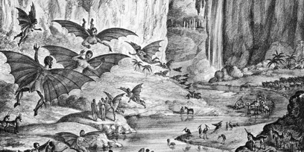
The 1835 affair — known as the Great Moon Hoax — took the form of six articles published in The Sun, a newspaper in New York City. Think of it like “War of the Worlds” but in newspaper form — reported as if true but completely made up. Although well-known astronomer John Herschel was named in the story, he wasn’t actually involved in the hoax. Richard Adams Locke was the reporter who invented the story. His main goal seemed to be to sell newspapers, but he also may have been poking fun at some of the more outlandish scientific claims of the day.