Proposing With A Contra ROM Hack

contra

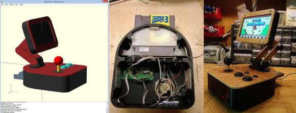
We’ve seen marriage proposals via modified Nintendo games before, but most of these put the proposal just after the first level. It’s one thing to have the old man in Zelda present your SO with a ring, but it’s another thing entirely to beat the game before getting on one knee. That’s what [Quinn] forced [Amy] to do when he proposed by modifying the ROM for Contra to display a proposal right before the end credits.

By tearing open a few cartridges, [Quinn] found himself with a bunch of EPROMs and NES cartridge PCBs. After grabbing the Contra ROM off the Internet, [Quinn] edited the game’s end screen to his proposal. This was then burned onto a 1 Megabit EPROM, soldered onto a cartridge, and put into the NES for his now-fiance to play. Once [Amy] and [Quinn] finished the game (without cheating, by the way), [Amy] saw her proposal and [Quinn] pulled out the ring.

No Nonsense Guide For Patching Into A Gaming Controller

patching-into-a-gaming-controller

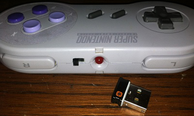
Here a straight-forward guide for tapping into the buttons on most gaming controllers. Why do something like this? Well there’s always the goal of conquering Mario through machine learning. But we hope this will further motivate hackers to donate their time and expertise developing specialized controllers for the disabled.

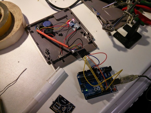
In this example a generic NES knock-off controller gets a breakout header for all of the controls. Upon close inspection of the PCB inside it’s clear that the buttons simply short out a trace to ground. By soldering a jumper between the active trace for each button and a female header the controller can still be used as normal, or can have button presses injected by a microcontroller.

The Arduino seen above simulates button presses by driving a pin low. From here you can develop larger buttons, foot pedals, or maybe even some software commands based on head movement or another adaptive technology.

Continue reading “No Nonsense Guide For Patching Into A Gaming Controller”

The 14th Game For The Nintendo Power Pad

[youtube=http://www.youtube.com/watch?v=6x23TWrInpI&w=580]

Released 25 years ago, the Nintendo Power Pad, a plastic mat that plugged into an NES, saw very limited success despite its prevalence in basements and attics. In total, only six games for the Power Pad were released in North America, and only 13 worldwide. The guys over at cyborgDino thought they should celebrate the sliver anniversary of the Power Pad by creating its 14th game, using an Arduino and a bit of playing around in Unity 3D.

The first order of business was to read the button inputs on the Power Pad. Like all NES peripherals, the Power Pad stores the state of its buttons in a shift register that can be easily read out with an Arduino. With a bit of help from the UnoJoy library, it was a relatively simple matter to make the Power Pad work as intended.

The video game cyborgDino created is called Axis. It’s a bit like a cross between Pong and a tower defense game; plant your feet on the right buttons, and a shield pops up, protecting your square in the middle of the screen from bouncing balls. It’s the 14th game ever created for the Power Pad, so that’s got to count for something.

Video of the game below.

Continue reading “The 14th Game For The Nintendo Power Pad”

Giving The VirtualBoy A VGA Out

Nintendo’s VirtualBoy – the odd console-inside-a-pair-of-goggles  and arguable ancestor of Nintendo’s 3DS – was a marvelous piece of technology for its time. In a small tabletop unit, you were able to play true 3D video games at an impressive 384 x 224 pixel resolution. Of course the VirtualBoy was a complete failure, but that doesn’t mean hardware tinkerers are leaving this wonderful system to video game collectors. [furrtek] has been playing around with his VirtualBoy and managed to add VGA out.

As a 3D system with two displays, any sort of video out was rightfully ignored by the VirtualBoy system designers. Still, [furrtek] wanted some sort of video out on his system, so he began poking around with a small FPGA board to generate some VGA signals.

The two displays inside the VirtualBoy aren’t your normal LCD display – as seen in this iFixit teardown. they’re really two linear LED arrays that generate a single line of 244 pixels, with mirrors scanning the line in the in the Y axis. These LED arrays are controlled by the VirtualBoy CPU through a series of shift registers, and by carefully tapping the lines of each LED array, [furrtek] was able to copy all the image data into the RAM of an FPGA.

After stuffing an XESS XULA-200 FPGA board inside the case of his VirtualBoy, [furrtek] wired up a few resistors for a DAC and installed a VGA out port on the underside of his console. Everything worked the first time he powered it up, and he began playing his VirtualBoy on his big screen TV.

Because [furrtek] is only reading one of the VirtualBoy’s displays, all the 3D data – and the main feature of the VirtualBoy – is lost when it’s displayed on a TV. 3D TVs do exist, though, and we’d love to see an improved version of this that captures data from both of the VirtualBoy displays.

You can see [furrtek]’s video of his mod in action below.

Continue reading “Giving The VirtualBoy A VGA Out”

NES Zapper Modified To Work With An Old Nintendo VS. Cabinet

nes-zapper-nintendo-vs

The company which [Eric Wright] works for recently bought a Nintendo VS. It had Ice Climber installed as one of the titles but they asked the vendor if it was possible to swap it out for the Duck Hunt ROM. They had the ROM but not a light gun that would work with the system. [Eric] suggested they buy it with Duck Hunt and hack an NES Zapper to work with the VS cabinet.

Let’s take a step back for a moment. The Nintendo VS was a coin-operated gaming cabinet you would find in an Arcade. Luckily there’s quite a bit of information about the original hardware on the web. Some research helped him discover that electronically the only difference between the arcade and home versions of the Zapper is that the sensor capture is inverted. This was fixed by replacing a transistor in the gun with a jumper wire. The next challenge was figuring out how to wire the gun up to the second controller port. And finally he patched the ROM to work with the incorrect PPU as the right chip was not easily sourced.

Continue reading “NES Zapper Modified To Work With An Old Nintendo VS. Cabinet”

Reading Game Boy Carts With I2C

rasgame

After seeing a Game Boy emulator for the first time, [Thijs] was amazed. A small box with just a handful of electronics that turns a Game Boy cartridge into a file able to be run on an emulator is simply magical. [Thijs] has learned a lot about GB and GBC cartridges in the mean time, but still thinks the only way to really learn something is to roll up your sleeves and get your hands dirty. Thus was born [Thijs]’ Game Boy cartridge dumper, powered by a pair of I2C port expanders and a Raspberry Pi.

Inspired by a build to dump ROMs off Super Nintendo games with the help of a Raspberry Pi, [Thijs] grabbed all the hardware necessary to create his own GB cart dumper. A DS Lite cartridge adapter provided the physical connection and a pair of MCP23017 I/O expanders – one soldered to a Slice of PI/O board – provided the electrical connections.

In the end, [Thijs] managed to dump the ROMs off the Japanese editions of Pokemon Yellow and Gold in about 13 minutes. This is a much slower transfer rate of 26 minutes per SNES cart in the post that gave [Thijs] the inspiration for this build. Still, [Thijs] will probably be the first to say he’s learned a lot from this build, especially after some problems with dumping the right banks from the cartridge.

One Game Controller Connects To Many Consoles

multi-controller-for-several-gaming-consoles2

[Dave Nunez] wanted arcade quality controls when gaming at home. The problem was he couldn’t decide on just one console to target with his build, so he targeted them all. What you see above is a single controller that connects to many different gaming rigs.

He took a simple-is-best approach, keeping the main goal of high-quality inputs at the forefront. To start, he built the face plate out of thick MDF to ensure it wouldn’t flex or bounce as he mashed the buttons. To keep the electronics as simple as possible he soldered connections to actual controller PCBs (well, reproductions of controllers), breaking each out to a separate DB9 connector on the back of the case. These connectors interface with one of the three adapter cables seen to the right. This lets the controller work with NES, SNES, and an Atari 2600 system.

To pull the enclosure together [Dave] designed the rounded corner pieces and cut them out with a CNC mill. These connect with flat MDF to make up the sides. To give it that professional look he filled the joints with Bondo and sanded them smooth before painting.