It’s safe to say that the Internet of Things is high on the list of buzzwords du jour. It was last seen rapidly ascending towards the Peak of Inflated Expectations on the Gartner Hype Cycle, and it seems that every startup you encounter these days is trying to place an IoT spin on their offering. Behind all the hype though lie some interesting wireless technologies for cheaply making very small microprocessors talk to each other and to the wider world.
Today we’d like to draw your attention to another wireless technology that might be of interest to Hackaday readers working in this area. UKHASnet is a wireless network developed from within the UK high-altitude ballooning community that uses cheap licence-exempt 868MHz radio modules in Europe and 915MHz in the Americas. The modules they are using have a surprisingly usable power output for licence exempt kit at 100mW, so the system has been designed for extensibility and bridging through nodes mounted on balloons, multirotors, or even seaborne buoys.
All UKHASnet packets are sent as human-readable plaintext ASCII, and the system borrows some of the features of amateur radio’s APRS. All packets are considered unreliable, all nodes repeat the packets they receive with their own node ID appended, and there are gateway nodes that make the packets available to the internet. There is a repeat number built into each packet to stop packets continuing ad infinitum.
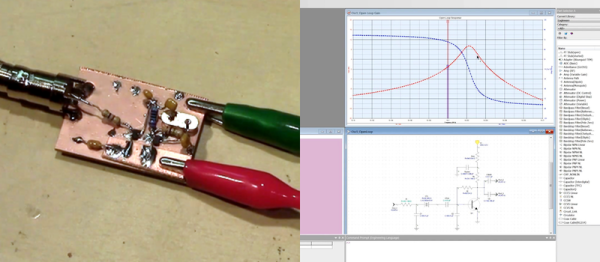
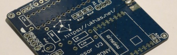
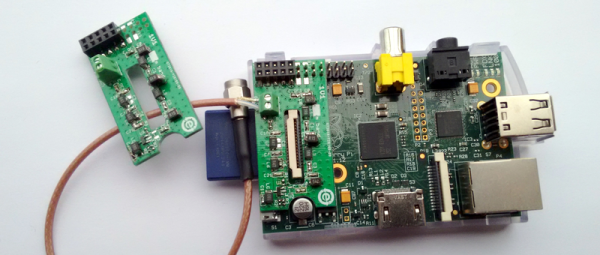
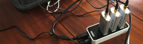
Building a node is a simple process, requiring only the radio module, a microcontroller, and a battery. As examples they provide an implementation for the Arduino, and one for the LPC810 microcontroller. Their preferred radio module is the HopeRF RFM69HW, however the system will be capable of running on other modules of the same type.
So far the UKHASnet people have proven the system over a 65km range, created nodes on the sea, attached it to quadcopters, and built a host of other nodes.
This network differs from its commercial counterparts in that it has no proprietary IP or licencing from a standards body. And despite the name, you don’t have to be in the UK to use it. All data is in the clear, and thus it is likely that you won’t see it in mass-market commercial products. But it is exactly these features that are likely to make it attractive to the maker community. Your scribe will probably not be the only person who goes away from this article to suggest that their local hackspace finds the space for a UKHASnet node.
This is the first time we’ve featured UKHASnet here at Hackaday. Plenty of projects using licence-free radio modules have made it onto these pages, though, including this extreme-range remote controller for model aircraft, and this weather station sensor network that could have probably found UKHASnet useful had its creator had it to hand.