What could possibly be better than printing out a few low-resolution voxels on a MakerBot? A whole lot of things, but how about getting those voxels with your own synthetic aperture radar? That’s what [Gregory Charvat] has been up to, and he’s documented the entire process for us.
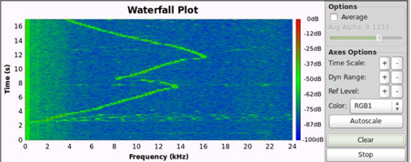
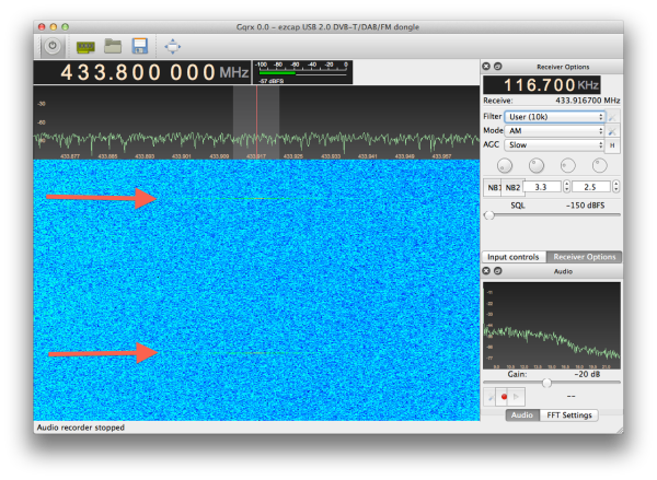
The build began with an ultra wideband impulse radar we saw a while ago. The radar is built from scraps [Greg] picked up on eBay, and is able to image a scene in the time domain, creating nice linear sweeps on a MATLAB plot when [Greg] runs in front of the horns.
With an impulse radar under his belt, [Greg] moved up the technological ladder to something that can produce vaguely intelligible images with his setup. The synthetic aperture radar made from putting his radar horns on the carriage of a garage door opener. The horns slowly scan back and forth along the linear rail, taking single impulse readings and adding them together in an image. In the video below, [Greg] is able to image a few pieces of copper pipe only a few inches in diameter. The necessary equipment for this build only cost [Greg] a few hundred bucks at the Dayton Hamvention, and a similar setup could be put together for even less.
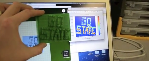
If building an X band impulse synthetic aperture radar isn’t impressive enough. [Greg] also 3D printed one of his radar images on a MakerBot. That’s just applying stlwrite to the 2D radar image and feeding it into MakerWare. Gotta have that blog cred, doe. It also makes for the best headline I’ve ever written.
Continue reading “DIY Ultra Wideband Impulse Synthetic Aperture Radar And A MakerBot”