Not every project has to be complicated– reinventing the wheel has its place, but sometimes you find a module or two that does exactly what you want, and the project is more than halfway done. That the kind of project [mircemk]’s Simple Retro Style VFO is — it’s a variable frequency oscillator for HAM and other use, built with just a couple of modules.
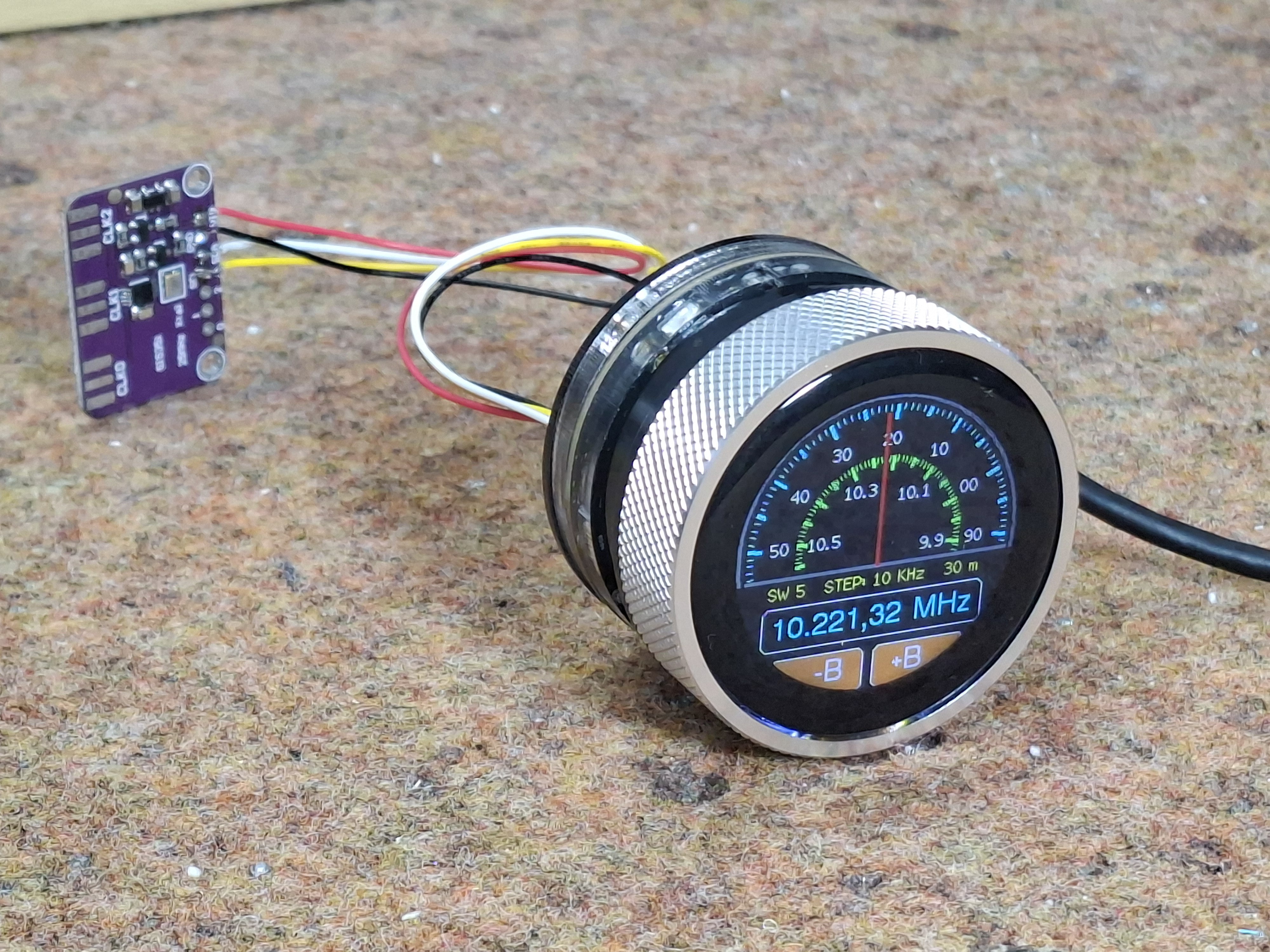
The modules in question are the SI5351 Clock Generator module, which is a handy bit of kit with its own crystal reference and PLL to generate frequencies up to 150 MHz, and the Elecrow CrowPanel 1.28inch-HMI ESP32 Rotary Display. The ESP32 in the CrowPanel controls the SI5351 module via I2C; control is via the rest of the CrowPanel module. This Rotary Display is a circular touchscreen surrounded by a rotary display, so [mircmk] has all the inputs he needs to control the VFO.
To round out the parts count, he adds an appropriate connector, plus a power switch, red LED and a lithium battery. One could include a battery charger module as well, but [mircmk] didn’t have one on hand. Even if he had, that still keeps the parts count well inside the single digits. If you like video, we’ve embedded his about the project below; if not the write up on Hackaday.io is upto [mircmk]’s typical standard.
People have been using the SI5351 to make VFOs for years now, but the addition of the round display makes for a delightfully retro presentation.
Thanks to [mircmk] for the tip.
Continue reading “Retro Style VFO Has Single-Digit Parts Count”