RFID Payment Ring Made From Dissolved Credit Card

RFID payment systems are one of those things that the community seems to be divided on. Some only see the technology as a potential security liability, and will go a far as to disable the RFID chip in their card so that it can’t be read by a would-be attacker. Others think the ease and convenience of paying for goods by tapping their card or smartphone on the register more than makes up for the relatively remote risk of RFID sniffers. Given the time and effort [David Sikes] put into creating this contactless payment ring, we think it’s pretty clear which camp he’s in.

Alright, so the whole ring making part sounds easy enough, but how does one get an RFID chip that’s linked to their account? Easy. Just call the bank and ask them for one. Of course, they won’t just send you out a little RFID chip and antenna to mount in your hacked up project. (If only things were so simple!) But they will send you a new card if you tell them your old one is getting worn out and needs a replacement. All you have to do when it gets there is liberate the electronics without damaging them.

[David] found that an hour or so in an acetone bath was enough to dissolve the plastic and expose the epoxy-encased RFID chip, assuming you scrape the outer layers of the card off first. He notes that you can speed this part of the process up considerably if you know the exact placement and size of the RFID chip; that way you can cut out just the area you’re interested in rather than having to liquefy the whole card.

Once you have your chip, you just need to mount it into a ring. [David] has designed a 3D printable frame (if you’ve got a high-resolution SLA machine, that is) which accepts the chip and a new antenna made from a coil of 38 AWG magnet wire. With the components settled into the printed frame, its off to a silicone mold and the liberal application of epoxy resin to encapsulate the whole thing in a durable shell.

If a ring is not personal enough for you, then the next step is getting the RFID chip implanted directly into your hand. There are even folks at hacker cons who will do that sort of thing for you, if you’re squeamish.

Continue reading “RFID Payment Ring Made From Dissolved Credit Card”

The $50 Ham: Dummy Loads

This is an exciting day for me — we finally get to build some ham radio gear! To me, building gear is the big attraction of amateur radio as a hobby. Sure, it’s cool to buy a radio, even a cheap one, and be able to hit a repeater that you think is unreachable. Or on the other end of the money spectrum, using a Yaesu or Kenwood HF rig with a linear amp and big beam antenna to work someone in Antartica must be pretty cool, too. But neither of those feats require much in the way of electronics knowledge or skill, and at the end of the day, that’s why I got into amateur radio in the first place — to learn more about electronics.

To get my homebrewer’s feet wet, I chose perhaps the simplest of ham radio projects: dummy loads. Every ham eventually needs a dummy load, which is basically a circuit that looks like an antenna to a transmitter but dissipates the energy as heat instead of radiating it an appreciable distance. They allow operators to test gear and make adjustments while staying legal on emission. Al Williams covered the basics of dummy loads a few years back in case you need a little more background.

We’ll be building two dummy loads: a lower-power one specifically for my handy talkies (HTs) will be the subject of this article, while a bigger, oil-filled “cantenna” load for use with higher power transmitters will follow. Neither of my designs is original, of course; borrowing circuits from other hams is expected, after all. But I did put my own twist on each, and you should do the same thing. These builds are covered in depth on my Hackaday.io page, but join me below for the gist on a good one: the L’il Dummy.

Continue reading “The $50 Ham: Dummy Loads”

A DIY EMC Probe From Semi-Rigid Coax And An SDR

Do you have an EMC probe in your toolkit? Probably not, unless you’re in the business of electromagnetic compatibility testing or getting a product ready for the regulatory compliance process. Usually such probes are used in anechoic chambers and connected to sophisticated gear like spectrum analyzers – expensive stuff. But there are ways to probe the electromagnetic mysteries of your projects on the cheap, as this DIY EMC testing setup proves.

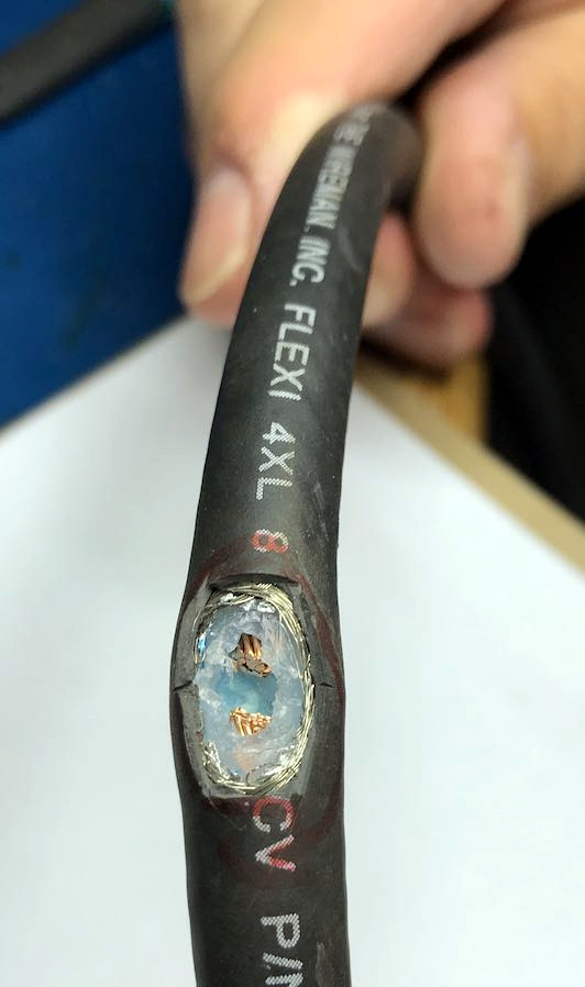
As with many projects, [dimtass]’ build was inspired by a video over on EEVblog, where [Dave] made a simple EMC probe from a length of semi-rigid coax cable. At $10, it’s a cheap solution, but lacking a spectrum analyzer like the one that [Dave] plugged his cheap probe into, [dimtass] went a different way. With the homemade probe plugged into an RTL-SDR dongle and SDR# running on a PC, [dimtass] was able to get a decent approximation of a spectrum analyzer, at least when tested against a 10-MHz oven-controlled crystal oscillator. It’s not the same thing as a dedicated spectrum analyzer – limited bandwidth, higher noise, and not calibrated – but it works well enough, and as [dimtass] points out, infinitely hackable through the SDR# API. The probe even works decently when plugged right into a DSO with the FFT function running.

Again, neither of these setups is a substitute for proper EMC testing, but it’ll probably do for the home gamer. If you want to check out the lengths the pros go through to make sure their products don’t spew signals, check out [Jenny]’s overview of the EMC testing process.

[via RTL-SDR.com]

Piezoelectric Antennas For Very, Very Low Frequencies

If you want to talk about antennas, the amateur radio community has you covered, with one glaring exception. Very low frequency and Extremely Low Frequency radio isn’t practiced very much, ultimately because it’s impractical and you simply can’t transmit much information when your carrier frequency is measured in tens of Hertz. There is more information on Extremely Low Frequency radio in Michael Crichton’s Sphere than there is in the normal parts of the Internet. Now there might be an easier way to play with VLF radiation, thanks to developers at the National Accelerator Laboratory. They’ve developed a piezoelectric transmitter for very long wavelengths.

Instead of pushing pixies through an antenna, this antenna uses a rod-shaped crystal of lithium niobate, a piezoelectric material. An AC voltage is applied to the rod makes it vibrate, and this triggers an oscillating electric current flow that’s emitted as VLF radiation. The key is that it’s these soundwaves bouncing around that define the resonant frequency, and the speed of sound in lithium niobate is a lot slower than the speed of light, but they’re translated into electric signals because of its piezoelectricity. For contrast, if this were a wire quarter-wave antenna it would be tens of kilometers long.

The application for this sort of antenna is ideally for where regular radio doesn’t work. Radio doesn’t work underwater, but nuclear subs trail an antenna out of the back to receive messages using Extremely Low Frequency radio. A walkie talkie doesn’t work in a mine, and this could potentially be used there. There is a patent for this piezoelectric antenna, so if anyone knows of a source of lithium niobate, put a link in the comments.

We’ve seen this trick before to make small antennas even smaller, but this is the first time we’ve seen it used in the VLF band, where it’s arguably even more impressive.

The $50 Ham: Checking Out The Local Repeater Scene

So far in this series, we’ve covered the absolute basics of getting on the air as a radio amateur – getting licensed, and getting a transceiver. Both have been very low-cost exercises, at least in terms of wallet impact. Passing the test is only a matter of spending the time to study and perhaps shelling out a nominal fee, and a handy-talkie transceiver for the 2-meter and 70-centimeter ham bands can be had for well under $50. If you’re playing along at home, you haven’t really invested much yet.

The total won’t go up much this week, if at all. This time we’re going to talk about what to actually do with your new privileges. The first step for most Technician-class amateur radio operators is checking out the local repeaters, most of which are set up exactly for the bands that Techs have access to. We’ll cover what exactly repeaters are, what they’re used for, and how to go about keying up for the first time to talk to your fellow hams.

Continue reading “The $50 Ham: Checking Out The Local Repeater Scene”

A New Digital Mode For Radio Amateurs

There used to be a time when amateur radio was a fairly static pursuit. There was a lot of fascination to be had with building radios, but what you did with them remained constant year on year. Morse code was sent by hand with a key, voice was on FM or SSB with a few old-timers using AM, and you’d hear the warbling tones of RTTY traffic generated by mechanical teletypes.

By contrast the radio amateur of today lives in a fast-paced world of ever-evolving digital modes, in which much of the excitement comes in pushing the boundaries of what is possible when a radio is connected to a computer. A new contender in one part of the hobby has come our way from [Guillaume, F4HDK], in the form of his NPR, or New Packet Radio mode.

NPR is intended to bring high bandwidth IP networking to radio amateurs in the 70 cm band, and it does this rather cleverly with a modem that contains a single-chip FSK transceiver intended for use in licence-free ISM band applications. There is an Ethernet module and an Mbed microcontroller board on a custom PCB, which when assembled produces a few hundred milliwatts of RF that can be fed to an off-the-shelf DMR power amplifier.

Each network is configured around a master node intended to use an omnidirectional antenna, to which individual nodes connect. Time-division multiplexing is enforced by the master so there should be no collisions, and this coupled with the relatively wide radio bandwidth of the ISM transceiver gives the system a high usable data bandwidth.

Whether or not the mode is taken up and becomes a success depends upon the will of individual radio amateurs. But it does hold the interesting feature of relying upon relatively inexpensive parts, so the barrier to entry is lower than it might be otherwise. If you are wondering where you might have seen [F4HDK] before, we’ve previously brought you his FPGA computer.

Bidirectional IP With New Packet Radio

There are a few options if you want to network computers on amateur radio. There are WiFi hacks of sort, and of course there’s always packet radio. New Packet Radio, a project from [f4hdk] that’s now on hackaday.io, is unlike anything we’ve seen before. It’s a modem that’s ready to go, uses standard 433 ISM band chips, should only cost $80 to build, and it supports bidirectional IP traffic.

The introductory documentation for this project (PDF) lays out the use case, protocol, and hardware for NPR. It’s based on chips designed for the 433MHz ISM band, specifically the SI4463 ISM band radio from Silicon Labs. Off the shelf amplifiers are used, and the rest of the modem consists of an Mbed Nucleo and a Wiznet W5500 Ethernet module. There is one single modem type for masters and clients. The network is designed so that a master serves as a bridge between Hamnet, a high-speed mesh network that can connect to the wider Internet. This master connects to up to seven clients simultaneously. Alternatively, there is a point-to-point configuration that allows two clients to connect to each other at about 200 kbps.

Being a 434 MHz device, this just isn’t going to fly in the US, but the relevant chip will work with the 915 MHz ISM band. This is a great solution to IP over radio, and like a number of popular amateur radio projects, it started with the hardware hackers first.