The MintyPi was a popular project that put a Raspberry Pi inside an Altoids tin to make a pocketable gaming handheld. Unfortunately, it’s not the easiest build to replicate anymore, but [jackw01] was still a fan of the format. Thus was born the Pi Tin—a clamshell handheld for portable fun!

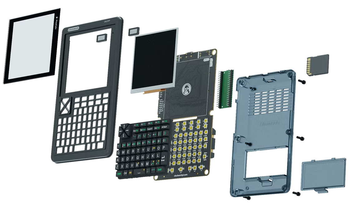
The build is based around the Raspberry Pi Zero 2W, which packs more power than the original Pi Zero into the same compact form factor. It’s combined with a 320 x 240 TFT LCD screen and a 2000 mAh lithium-polymer battery which provides power on the go.
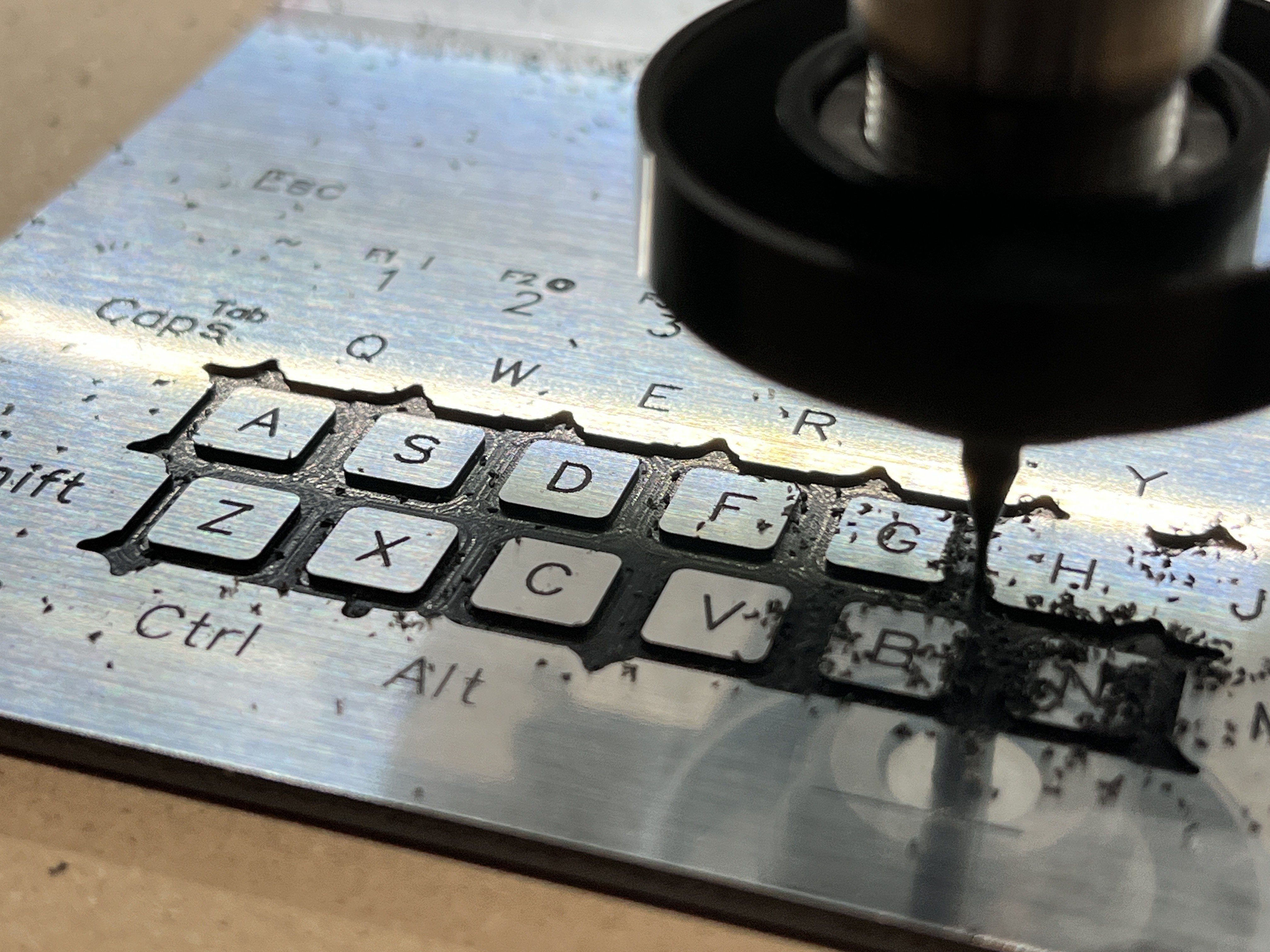
There are also a pair of custom PCBs used to lace everything together, including the action buttons, D-pad, and power management hardware. Depending on your tastes, you have two main enclosure options. You can use the neat 3D printed clamshell seen here in beautiful teal, or you can go with the classic Altoids tin build—just be careful when you’re cutting it to suit! Files can be found on GitHub for the curious.
We love a good handheld project around these parts; it’s particularly awesome how much gaming you can fit in your pocket given the magic of the Raspberry Pi and modern emulation. If you’re cooking up your own little retro rig, don’t hesitate to let us know!