One of the recurring themes of science fiction is the robot. From such icons as C-3PO and R2D2 in Star Wars to WALL-E and Eve, robots have always had a certain appeal. Inexpensive microcontrollers like the Arduino have opened up the world of robotics to more people. [JohnFin] has done just this. By linking two Arduinos as the brain, he has created a voice controlled robot he calls S.P.A.R.C. (Sentry/Project Assistant/Robot Companion).
It began when he received a robotic arm for Christmas and was disappointed by it. Instead of simply building a better arm, he got “carried away” and built an entire robot instead. The entire project took three months, most of which he spent learning programming.
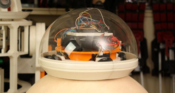
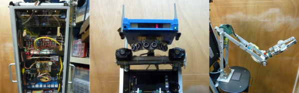
SPARC has three sonar sensors for detecting obstacles and movement, an arm and a couple of interchangeable hands for holding objects, and an EasyVR Arduino Shield for the voice control. The robot’s “eyes” are an LED ‘KITT’ scanner and an AN6884 VU meter chip that flashes the “eyes” when the robot speaks. It carries an onboard smartphone to look up weather, play music from the phone’s SD card, and GPS functions.
SPARC can respond to a range of commands and games including “follow me” and “singing.” [JohnFin] has also added a “sequencer” function to record and playback a series of commands. A video of this feature can be found after the break.
Continue reading “SPARC: A Voice Controlled Robot Sings Sweetly In DTMF”