Antweight Combat Robot Tips, Shared From Experience

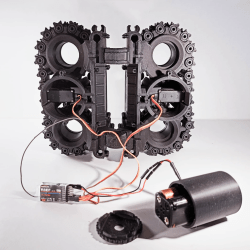
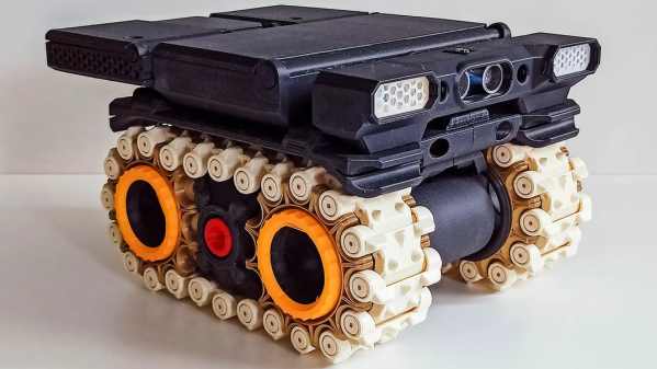
[Harry]’s newest robot, the MotherLoader V2, looks fantastic but was ultimately more of a learning experience and test bed for some experimental features. Luckily for us, [Harry] created a lengthy write-up detailing everything that he tried and revised.

3D printing and aluminum both feature heavily in antweight robots, in part because when contestants are limited to 150 grams it’s safe to say that every bit counts. We recommend reading [Harry]’s entire article to get all the details, but here are some of the bigger takeaways.

Treads provide a lot of contact surface, but there are a lot of ways they can go wrong. Pliability and grip have to be good matches for the robot’s design, otherwise the tread might bunch up or otherwise perform poorly when trying to maneuver. [Harry] had several dud efforts, but ended up with a great result by borrowing an idea from another competitor: composite tracks.

These have an inner track printed from flexible TPU filament, and an outer layer formed by casting silicone directly onto the 3D printed core. It’s a somewhat involved process, but the result is a durable and custom-fitted inner track on the inside, and a softer grip outside. Best of both worlds, and easily tailored to match requirements.

Speaking of TPU, [Harry] discovered that it can be worth printing structural parts with TPU. While ABS is usually the material of choice for durable components, printing solid parts in TPU has a lot to recommend it when it comes to 150 gram robots. Not only can TPU parts be stiff enough to hold up structurally, but they can really take a beating and happily spring back into shape afterwards.

We’ve seen [Harry]’s work before on antweight combat robots, and it’s always nice to peek behind the scenes and gaze into the details. Especially for processes like this, where failures are far more educational than successes.

Robot Dog Has Animal Magnetism

Robot “dogs” are all the rage lately, but you probably haven’t seen one that can climb up a wall. Researchers in Korea have made one that can, assuming the wall is made out of a metal that a magnet can stick to at least. The robot, MARVEL or magnetically adhesive robot for versatile and expeditious locomotion, might be pressing its luck on acronyms, but it is pretty agile as you can see in the video below. Tests showed the robot walking on walls and ceilings. It can cross gaps and obstacles and can even handle a curved storage tank with paint and rust.

The robot weighs 8 kilograms (17.6 pounds), can carry 2 – 3 kg of payload, and operates without a tether. Each foot contains both an electropermanent magnet and magnetorheological elastomers. If you haven’t seen them before, an electropermanent magnet, or EPM, is a magnet that can be turned on or off electronically. The elastomer is a polymer containing ferromagnetic particles that can alter the material’s properties in response to a magnetic field.

EPMs have two parts. One part is a simple permanent magnet. The other is a soft core easily magnetized by a surrounding coil. If you magnetize the soft core to oppose the permanent magnet, the fields cancel out, effectively turning off the magnet. If you magnetize it the other way, it reinforces the field.

This is better than an electromagnet in this application because turning the magnet on or off only requires a brief pulse. If you want your robot to hang out on the ceiling with Spider Man indefinitely, you don’t have to worry about draining your batteries while keeping an electromagnet engaged.

Overall, an interesting robot. Most wall-climbing robots we’ve seen are pretty lightweight. We don’t see nearly as many that can have the feeling of clinging to the ceiling.

Continue reading “Robot Dog Has Animal Magnetism”

Differential Swerve Drive Is Highly Maneuverable

There are a variety of wheel designs out there that can provide for rotation and translation in various directions. The differential swerve drive, though, as demonstrated by [WildWillyRobots], uses regular wheels on a complex mount to achieve impressive directional flexibility.

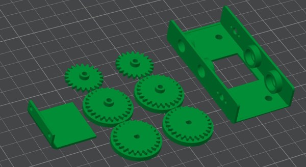
The design uses a regular round wheel mounted on an axle, which has a gear on one end. This allows the wheel to be driven. The wheel and axle is mounted upon a circular carrier, which is then fitted with a pair of surrounding gears on bearings. Differentially driving these gears changes the way the drive behaves. With both gears driven in the same direction, the wheel rotates on its vertical axis to point in different directions. If both gears are driven in opposite direction, the wheel itself is driven. Relatively varying the speed of both gears allows the direction and drive of the wheel to be controlled. The result is a wheel that can rotate to any angle, and then be driven forwards or backwards as well.

Fitting a set of these wheels to a robot creates a highly maneuverable platform. As a bonus, it doesn’t have the drawback of poor grip that is common with various omniwheel-type designs.

Continue reading “Differential Swerve Drive Is Highly Maneuverable”

Omniwhegs Are Awesome Times Two

What’s the strangest wheel? The omniwheel. Unless you count whegs — “wheel legs” — as wheels. This research paper from Shanghai Technical University explores a mash-up of the two ideas, where the wheels roll as standard omniwheels until a servo on the axle unfurls them into their whegs configuration. The result? OmniWhegs!

The resulting vehicle is a bit of a departure from the original whegs concept, which used compliant mechanisms which passively balanced the force across the legs. Here, the omniwhegs are rigid and actually use a synchronization routine that you can see in the video embedded below.

If you can’t get enough omniwheels, you’re not alone. Here’s a rare three-wheeler, and here’s an omniwheel made of MDF. We haven’t seen enough whegs-based bots, but OutRunner is pretty astounding, and we think deserves a second look.

We’ve also seen wheels that convert to whegs before, but without the omni.  And we don’t know if that one ever made it out of render-of-a-robot phase.

So kudos to the Shanghai team for taking the strangest possible wheels and actually building them!

Continue reading “Omniwhegs Are Awesome Times Two”

Gaze Upon The Swimming Mechanical Stingray, Made With LEGO

Stingrays have an elegant, undulating swimming motion that can be hypnotic. [Vimal Patel] re-created this harmony with his fantastic mechanical mechanical stingray using LEGO pieces and a LEGO Technics Power Functions motor. The motor is set in a clever arrangement that drives the motion remotely, so that it and electrical elements can stay dry.

The mechanical stingray sits at the end of a sort of rigid umbilical shaft. This shaft connects the moving parts to the electrical elements, which float safely on the surface. This leaves only the stingray itself with its complex linkages free to move in the water, while everything else stays above the waterline.

We’ve seen some impressive LEGO creations before, like this race car simulator and pneumatic engine, and the mechanical action in this stingray is no exception. Interested in making your own? The part list and build directions are available online, and you can see it in action in the video embedded below.

Continue reading “Gaze Upon The Swimming Mechanical Stingray, Made With LEGO”

The Robots Of Fukushima: Going Where No Human Has Gone Before (And Lived)

The idea of sending robots into conditions that humans would not survive is a very old concept. Robots don’t heed oxygen, food, or any other myriad of human requirements. They can also be treated as disposable, and they can also be radiation hardened, and they can physically fit into small spaces. And if you just happen to be the owner of a nuclear power plant that’s had multiple meltdowns, you need robots. A lot of them. And [Asianometry] has provided an excellent synopsis of the Robots of Fukushima in the video below the break.

Starting with robots developed for the Three Mile Island incident and then Chernobyl, [Asianometry] goes into the technology and even the politics behind getting robots on the scene, and the crossover between robots destined for space and war, and those destined for cleaning up after a meltdown.

The video goes further into the challenges of putting a robot into a high radiation environment. Also interesting is the state of readiness, or rather the lack thereof, that prompted further domestic innovation.

Obviously, cleaning up a melted down reactor requires highly specialized robots. What’s more, robots that worked on one reactor didn’t work on others, creating the need for yet more custom built machines. The video discusses each, and even touches on future robots that will be needed to fully decommission the Fukushima facility.

For another look at some of the early robots put to work, check out the post “The Fukushima Robot Diaries” which we published over a decade ago.

Continue reading “The Robots Of Fukushima: Going Where No Human Has Gone Before (And Lived)”

Radial Vector Reducer Rotates At Really Relaxed Velocity

When [Michael Rechtin] learned about Radial Vector Reducers, the underlying research math made his head spin, albeit very slowly. Realizing that it’s essentially a cycloidal drive meshed with a planetary gear set, he got to work in CAD and, in seemingly no time, had a design to test. You can see the full results of his experiment in the video below the break. Or head on out to Thingiverse to download the model directly.

[Michael] explains that while there are elements of a cycloidal drive, itself a wonderfully clever gear reduction mechanism, the radial vector reducer actually has more bearing surfaces, and should be more durable as a result. Two cycloidal disks are driven by a planetary gear reduction for an even greater reduction, but they don’t even spin, they just cycle in a way that drives the outer shell, setting them further apart from standard cycloidal drives.

How would this 3D printed contraption hold up? To test this, [Michael] built a test jig with a NEMA 23 stepper providing the torque, and an absurd monster truck/front loader wheel — also printed — to provide traction in the grass and leaves of his back yard. He let it drive around its tether for nearly two weeks before disassembling it to check for wear. How’d it look? You’ll have to check the video to find out.

If you aren’t familiar with cycloidal drives, check out this fantastic explanation we featured. As for planetary drives, what better way to demonstrate it than by an ornamental planetary gear clock!

Continue reading “Radial Vector Reducer Rotates At Really Relaxed Velocity”