A powerful robot awaiting for a verbal command to crush its foes might sound like something from a science fiction film, but now it’s a permanent fixture of the [Making Stuff] garage. (Video, embedded below.) Thankfully this robot’s sworn enemy are aluminum cans, and the person controlling it with their voice isn’t a maniacal scientist, just a guy who’s serious about recycling. Well, we hope so anyway.
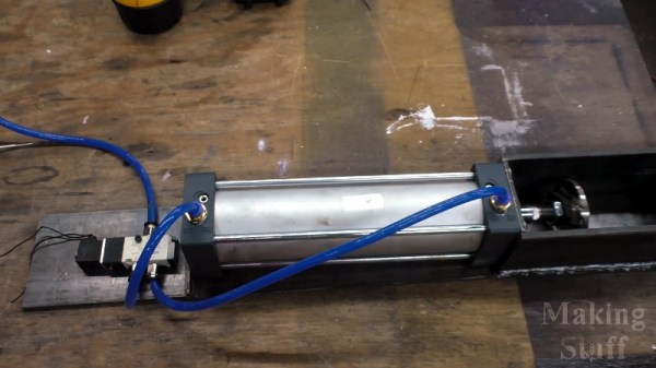
The star of the show is a heavy duty wall-mounted can crusher that [Making Stuff] built from some scrap steel and a pneumatic cylinder hooked up to the garage’s compressed air system. A solenoid operated valve allows an Arduino with attached ESP-01 to extend the cylinder whenever the appropriate command comes over the network. In this case, the goal was to tie the crusher into Google Assistant so a can would get smallified whenever one of Google’s listening devices heard the trigger phrase.

Obviously, those who’d rather keep Big Data out of their recycling bin don’t have to go down the same path. But that being said, having to give a specific voice command to activate the machine does provide a certain level of operational safety. At least compared to trusting some eBay sensor to tell the difference between an aluminum can and a fleshy appendage.
After crushing a few cans with his new toy, [Making Stuff] noticed a fairly troubling flaw in the design. Each time a can was crushed he had to reach into the maw of the machine to push its little flattened carcass out of the way. In other words, he was one bad line of code away from having one good hand.
The solution ended up being a new hose that runs from the exhaust port of the valve to the crushing chamber: once the cylinder retracts, the air exiting the valve pushes the crushed can out the rear of the machine and into a waiting pail underneath. Very slick.
Even if you’re not interested in the voice control aspect, this is a great design to base your own can crusher on. While it’s always a treat when a fully automatic crusher comes our way, we’ll admit the challenges of getting one to work reliably probably aren’t worth the hassle.
Continue reading “Pneumatic Can Crusher Awaits Your Command”