Talking Ohmmeter Also Spits Out Color Bands For You

If you’ve got a resistor and you can’t read the color bands (or they’re not present), you can always just grab a multimeter and figure out its value that way. [Giacomo Yong Cuomo] and [Sophia Lin] have built an altogether different kind of ohmmeter, that can actually spit out color values for you, and even read the resistance aloud. It’s all a part of their final project for their ECE 4760 class.

The build is based around a Raspberry Pi Pico. It determines the value of a resistor by placing it in a resistor divider, with the other reference resistor having a value of 10 kΩ. The resistor under test is connected between the reference resistor and ground, while the other leg of the reference resistor is connected to 3.3 V. The node between the two resistors is connected to the Pi Pico’s analog-to-digital converter pin. This allows the Pico to determine the voltage at this point, and thus calculate the test resistor’s value based on the reference resistor’s value and the voltages involved.

A large fake resistor provides user feedback. It’s filled with addressable LEDs, which light up the appropriate color bands depending on the test resistor’s value. It’s capable of displaying both 3-band, 4-band, and 5-band color configurations. While six-band resistors do exist, the extra band is typically used for denoting temperature coefficients which can’t readily be determined by this simple test. It can also play audio files to announce the resistance value over a speaker.

It’s a neat project that surely taught the duo many useful skills for working with microcontrollers. Plus, it’s kinda fun — we love the big glowing resistor. We’ve featured some other fancy resistors before, too!

Continue reading “Talking Ohmmeter Also Spits Out Color Bands For You”

DIY Pneumatic Actuator Does Great In Action

Pneumatic actuators can be powerful and fast, making them very useful for all kinds of mechanical jobs. [Michael Rechtin] decided that while he could buy them off-the-shelf, he preferred to see if he could make his own via 3D printing. Despite the challenges, he succeeded!

Part of his success is because he knew when to take advantage of the strengths of 3D printed parts, and where they wouldn’t perform so well. To that end, the main body of the cylinder is actually a piece of PVC pipe. That’s because manufactured PVC pipe is far smoother and more regular than what you could reasonably achieve with a most 3D printers. The end caps, however, were printed and tapped to take standard air fittings. The piston was printed too, fitted with a steel cylinder rod and O-rings for sealing.

The double-acting cylinder performed remarkably well in testing, easily skewering an orange. The initial version did leak a touch, but later revisions performed better. Springs were also fitted for damping hits at either end which improved longevity, with a test rig racking up over 10,000 cycles without failure.

We love a design that is both easy to build at home and capable of great performance. We’ve featured some neat open-source pneumatic builds before, too.

Continue reading “DIY Pneumatic Actuator Does Great In Action”

Ultra-Basic Thermal Camera Built Using Arduino Uno

Thermal cameras can cost well into the five-figure range if you’re buying high-resolution models with good feature sets. New models can be so advanced that their export and use is heavily controlled by certain countries, including the USA. If you just want to tinker at the low end, though, you don’t have to spend a lot of scratch. You can even build yourself something simple based on an Arduino Uno!

The build uses Panasonic’s cheap “Grid-EYE” infrared array as the thermal sensor, in this case, a model with an 8×8 array of thermopiles. It’s not going to get you any fancy images, especially at long range, but you can use it to get a very blocky kind of Predator-vision of the thermal radiation environment. It’s a simple matter of hooking up the Grid-EYE sensor to the Arduino Uno over I2C, and then spitting out the sensor’s data in a nice visual form on a cheap TFT screen.

It’s a great introduction to the world of thermal imaging. There’s no better way to learn how something works by building a working example yourself. We’ve featured a few similar projects before, too; it’s all thanks to the fact that thermal sensors are getting cheaper and more accessible than ever!

Hacker Tactic: Internal ESD Diode Probing

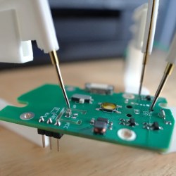
Humans are walking high voltage generators, due to all the friction with our surroundings, wide variety of synthetic clothes, and the overall ever-present static charges. Our electronics are sensitive to electrostatic discharge (ESD), and often they’re sensitive in a way most infuriating – causing spurious errors and lockups. Is there a wacky error in your design that will repeat in the next batch, or did you just accidentally zap a GPIO? You wouldn’t know until you meticulously check the design, or maybe it’s possible for you to grab another board.

Thankfully, in modern-day Western climates and with modern tech, you are not likely to encounter ESD-caused problems, but they were way more prominent back in the day. For instance, older hackers will have stories of how FETs were more sensitive, and touching the gate pin mindlessly could kill the FET you’re working with. Now, we’ve fixed this problem, in large part because we have added ESD-protective diodes inside the active components most affected.

These diodes don’t just help against ESD – they’re a general safety measure for protecting IC and transistor pins, and they also might help avoid damaging IC pins if you mix. They also might lead to funny and unexpected results, like parts of your circuit powering when you don’t expect them to! However, there’s an awesome thing that not that many hackers know — they let you debug and repair your circuits in a way you might not have imagined.

Continue reading “Hacker Tactic: Internal ESD Diode Probing”

Upgrade Puts A Lot Of Zeroes On Kit-Built Frequency Counter

If there’s anything more viscerally pleasing than seeing an eight-digit instrument showing a measurement with all zeroes after the decimal point, we’re not sure what it could. Maybe rolling the odometer over to another 100,000 milestone?

Regardless, getting to such a desirable degree of accuracy isn’t always easy, especially when the instrument in question is a handheld frequency counter that was built from a kit 23 years ago. That’s the target of [Petteri Aimonen]’s accuracy upgrade, specifically by the addition of a custom frequency reference module. The instrument is an ELV FC-500, which for such an old design looks surprisingly modern. Its Achille’s heel in terms of accuracy is the plain crystal oscillator it uses as a frequency standard, which has no temperature compensation and thus drifts by about 0.2 ppm per degree.

For a mains-powered lab instrument, the obvious solution would be an oven-controlled crystal oscillator. Those are prohibitive in terms of space and power for a handheld instrument, so instead a VCTCXO — voltage-controlled, temperature-compensated crystal oscillator — was selected for better stability. Unfortunately, no such oscillators matching the original 4.096-MHz crystal spec could be found; luckily, a 16.384-MHz unit was available for less than €20. All that was required was a couple of flip-flops to divide the signal by four and a bit of a bodge to replace the original frequency standard. A trimmer allows for the initial calibration — the “VC” part — and the tiny PCB tucks inside the case near the battery compartment.

We enjoyed the simplicity of this upgrade — almost as much as we enjoyed seeing all those zeroes. When you know, you know.

Wio Terminal Makes Passable Oscilloscope

There was a time when getting a good oscilloscope not only involved a large outlay of capital, but also required substantial real estate on a workbench. The situation has improved considerably for the hobbyist, but a “real” scope can still cost more than what a beginner is looking to spend. Luckily, plenty of modern microcontrollers are capable of acting as a basic oscilloscope in a pinch, provided there’s a display available to interface with it. Combined with the right software, the Wio Terminal looks like a promising option.

The Wio Terminal is a platform gaining some popularity due to its fairly capable SAMD51 microcontroller and also its integration with a display and a number of input buttons. On the hardware side, [mircemk] mounted the Terminal in a convenient vertical orientation and broke out a pair of connectors for the inputs.

But it’s the software that really makes this project work. [Play With Microcontroller] originally developed the firmware for the PIC24 back in 2017, but ported the code over to the Wio Terminal a couple years back. Noting that the microcontroller is not particularly fast, the project doesn’t exactly match the specifications or capabilities of a commercial unit. But still, it does an impressive job of recreating the experience of using a modern digital scope

The Wio Terminal is a device we’ve seen around here for a few unique projects, among them a device for preventing repetitive strain injuries while using a computer mouse and another that is a guide for game development in MicroPython. And if you’re just itching to port oscilloscope software to accessible but under-powered microcontrollers, be sure to check out [mircemk]’s other oscilloscope projects like this one built around the STM32 microcontroller.

Continue reading “Wio Terminal Makes Passable Oscilloscope”

This Pogo Pin Test Fixture Keep Your SMDs From Taking Flight

There’s no denying how useful surface mount technology is, and how enabling the ability to make really small circuits has become. It comes at a price, though; most of us probably know what it’s like for the slightest wrong move to send a part the size of a grain of sand into another dimension.

To help make testing these parts a little easier, [IMSAI Guy] has come up with this clever little SMD test fixture. It’s designed to hook up to another custom board, which in turn connects to a wonderful old Hewlett-Packard 4275A LCR meter. The jig is based on two pogo pins mounted directly across from each other on a scrap of single-clad PCB. The spring-loaded contacts, which short together when not in use, are pulled apart to load an SMD part, like the 1-μH inductors shown in the video below. The pins hold the component firmly and make good electrical contact, allowing hands-free testing without the risk of an errant touch of the test probes sending it flying.

While the test fixture works well for larger SMDs, we could see this being a bit fussy for smaller parts. That would be easy enough to fix with perhaps some 3D-printed arms that retract the pogo pins symmetrically, holding them open until the part is loaded. A centering fixture might help too, as would a clear shield to contain any parts that get the urge to go for a ride. But, for the tactical application [IMSAI Guy] has in mind, this sure seems like enough.

Just getting into surface mount? If so, you might want to check out this handy guide to the often cryptic markings used on SMD parts.

Continue reading “This Pogo Pin Test Fixture Keep Your SMDs From Taking Flight”