A lamp used to be simple thing: just stick a filament in a glass bulb, pass a current through it and behold! Let there be light. A bigger lamp meant a larger filament, taking more power and a larger envelope. Now we’ve moved on a bit, and it’s all about LEDs. There really isn’t such a thing as ‘just an LED,’ these are semiconductor devices, made from relatively exotic materials (OK, not just plain old silicon anyway) and there is quite a lot of variety to choose from, and a bit of complexity in selecting them.
For [Torque Test Channel] the efficiency of conversion from electrical power to radiant power (or flux) is the headline figure of interest, which prompted them to buy a bunch of lamps to compare. To do the job justice that requires what’s known in the business as an integrating sphere (aka an Ulbricht sphere), but being a specialist device, it’s a bit pricey for the home gamer. So naturally, they decided to build the thing themselves.
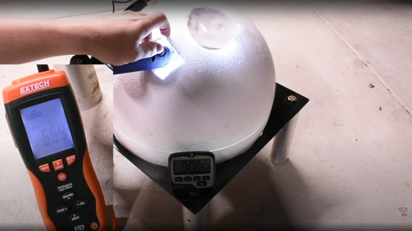
Firstly they did the sensible thing, and shipped off their test units to a metrology lab with the ‘proper’ equipment, to get a baseline to calibrate against. Next they set about using some fairly common materials to construct their sphere. The basic idea is quite simple; it has a uniform diffuse internal surface, which ensures that all photons emitted by a source can be measured at the appropriate measurement port, regardless of the angle they are emitted from the source. This way, the total radiated power can be determined, or at least estimated, since there will be a degree of absorption.
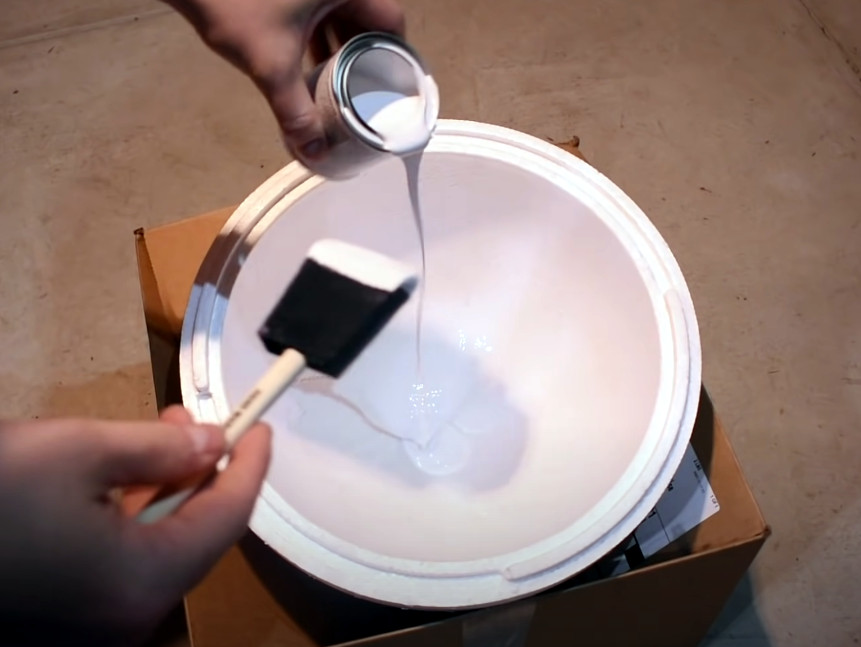
Anyway, after a couple of false starts with coating the internal surface, they came to the conclusion that mixing barium sulphate into the paint, and then a bit of a rub-down with sandpaper, gave the required pure white, diffuse surface.
The results from their testing, using a lux meter inserted into one of the other ports, showed a pretty good correspondence between their measured lux figure and the lab-determined lumens figure. Since one lux is defined as one lumen per square meter, they seemed to get lucky and found a consistent ten-to-one ratio between their observed value and the lab. This factor will be simply due to the physical setup of their contraption, but an encouraging result so far anyway. And what about the bottom line? Did those test units deliver their promised lumen output? It would seem that they pretty much did.
When it rains, it pours. Just a few hours ago we saw another DIY approach to building an integrating sphere, this time using a small cannonball mold of all things. Before that we hadn’t actually seen too many light measurement projects, save this old one that used the chipKIT. Continue reading “Is Your Flashlight A Lumen Liar? Build A DIY Integrating Sphere”