Soldering irons and their tips come in a wide range of formats and styles, with the (originally Hakko) T12 being one of the more interesting offerings. This is because of how it integrates not only the tip and heating element, but also a thermocouple and everything else in a self-contained package. In a recent video [Big Clive] decided to not only poke at one of these T12 tips, but also do a teardown.
 These elements have three bands, corresponding to the power supply along with a contact for the built-in thermocouple. After a quick trip to the Vise of Knowledge, [Clive] allows us a glimpse at the mangled remnants of a T12, which provides a pretty good overview of how these tips are put together.
Perhaps unsurprisingly, most of the length is a hollow tube through which the wires from the three contacts run. These power the ceramic heating element, as well as provide the soldering iron handle access to the thermocouple that’s placed near the actual tip.
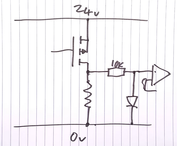
With a simple diagram [Clive] explains how these T12 elements are then used to regulate the temperature, which isn’t too distinct from the average soldering iron with ceramic heating element, but it’s still nice to have it all integrated rather than having to try to carefully not damage the ceramic heater while swapping tips with the average soldering iron.
Continue reading “Understanding The T12 Style Soldering Iron Tip”