If there’s one thing you need in a woodshop, it’s more clamps. There are bar clamps, pipe clamps, spring clamps, and trigger clamps, but for one task in the workshop, no clamp does the job just right. Gluing up panels – a few wide pieces of wood joined on edge – either requires more clamps than you have or cauls, devices that press down on the boards vertically while the clamps press the board together horizontally.
[Andrew Klein] has just invented a new type of clamp for this task, proving once again that not all problems are solved, and there’s still some places where an invention can pop out of mid-air.
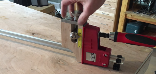
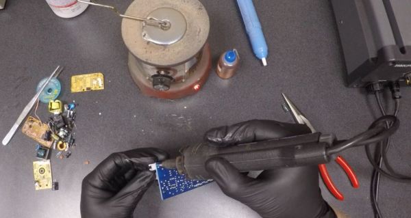
The new clamps are a modification to traditional bar clamps that allow for two clamps to interlock. On each of the ‘working’ ends of the clamps, there are two adjustment handles. The first screws the clamp horizontally, just like any bar or pipe clamp. The second adjustment handle moves a bearing up and down. When this bearing meshes with a riser on the mating end of another clamp, the two clamps are pressed together vertically.
The new clamps are effectively clamps and cauls, able to push material together from side to side and top to bottom. The new clamps work, too. In the video below, you can see [Andrew] gluing up a panel. When the vertical adjustment wheel is loosened, the boards come apart vertically. When the vertical adjustment wheel is tightened, the boards are perfectly in line with each other, both edge to edge and face to face.
Continue reading “Clamps, Cauls, And The Mother Of Invention” →
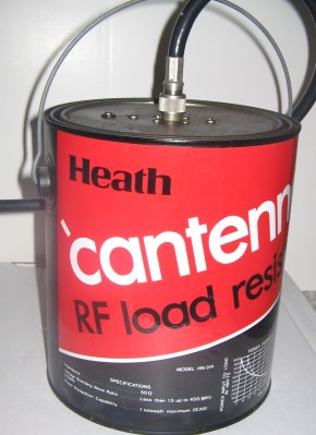 The Cantenna (not the Pringle’s kind; see right) was a famous dummy load design when Heathkit was in business. It was a single carbon rod immersed in a paint can full transformer oil (which we now know was full of
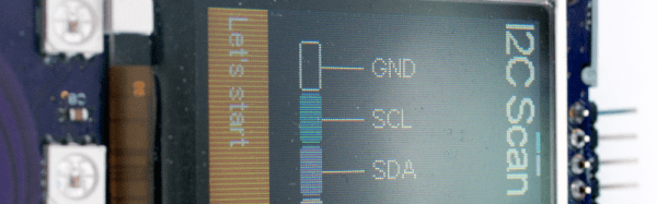
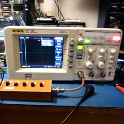 If your scope is relatively recent, like this side of the late 1990s, it might support National Instrument’s