Once upon a time, a remote controlled (RC) car was something you’d buy at Radio Shack or your local hobby store. These days, you can print your own, complete with suspension, right at home, as this project from [Logan57] demonstrates.
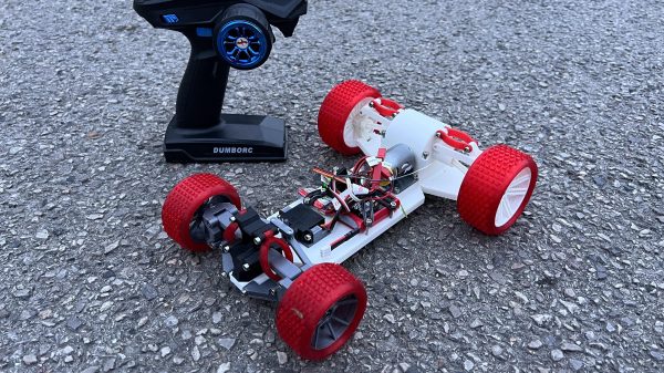
The design uses standard off-the-shelf hobby-grade components, with a brushed motor and controller for propulsion, and small metal gear servo for steering. The latter is a smart choice given there’s no servo saver in the design. Save for the fasteners and bearings, all the other parts are 3D printed. The hard components are produced in PETG or PLA, while flexible TPU is used for both the tires and the spring elements in the suspension system. It’s a double-wishbone design, and should serve as a good education should you later find yourself working on a Mazda Miata.
Building your own RC car isn’t just fun, it opens up a whole realm of possibilities. Sick of boring monster trucks and race cars? Why not build a 10×10 wheeler or some kind of wacky amphibious design? When you do, we’ll be waiting by the tipsline to hear all about it. Video after the break.