3D-Printed Tourbillon Demo Keeps The Time With Style

It may only run for a brief time, and it’s too big for use in an actual wristwatch, but this 3D-printed tourbillon is a great demonstration of the lengths watchmakers will go to to keep mechanical timepieces accurate.

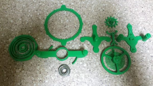
For those not familiar with tourbillons, [Kristina Panos] did a great overview of these mechanical marvels. Briefly, a tourbillon is a movement for a timepiece that aims to eliminate inaccuracy caused by gravity pulling on the mechanism unevenly. By spinning the entire escapement, the tourbillon averages out the effect of gravity and increases the movement’s accuracy. For [EB], the point of a 3D-printed tourbillon is mainly to demonstrate how they work, and to show off some pretty decent mechanical chops. Almost the entire mechanism is printed, with just a bearing being necessary to keep things moving; a pair of shafts can either be metal or fragments of filament. Even the mainspring is printed, which we always find to be a neat trick. And the video below shows it to be satisfyingly clicky.

[EB] has entered this tourbillon in the 3D Printed Gears, Pulleys, and Cams Contest that’s running now through February 19th. You’ve still got plenty of time to get your entries in. We can’t wait to see what everyone comes up with!

Continue reading “3D-Printed Tourbillon Demo Keeps The Time With Style”

Fail Of The Week: 3D Printed Worm Gear Drive Project Unveils Invisible Flaw

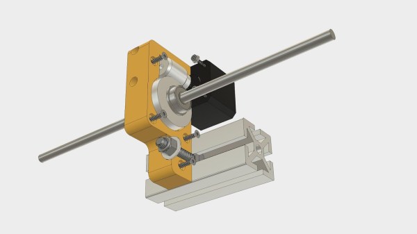
All of us would love to bring our projects to life while spending less money doing so. Sometimes our bargain hunting pays off, sometimes not. Many of us would just shrug at a failure and move on, but that is not [Mark Rehorst]’s style. He tried to build a Z-axis drive for his 3D printer around an inexpensive worm gear from AliExpress. This project was doomed by a gear flaw invisible to the human eye, but he documented the experience so we could all follow along.

We’ve featured [Mark]’s projects for his ever-evolving printer before, because we love reading his well-documented upgrade adventures. He’s not shy about exploring ideas that run against 3D printer conventions, from using belts to drive the Z-axis to moving print cooling fan off the print head (with followup). And lucky for us, he’s not shy about document his failures alongside the successes.

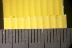
He walks us through the project, starting from initial motivation, moving on to parts selection, and describes how he designed his gearbox parts to work around weaknesses inherent to 3D printing. After the gearbox was installed, the resulting print came out flawed. Each of the regularly spaced print bulge can be directly correlated to a single turn of the worm gear making it the prime suspect. Then, to verify this observation more rigorously, Z-axis movement was measured with an indicator and plotted against desired movement. If the problem was caused by a piece of debris or surface damage, that would create a sharp bump in the plot. The sinusoidal plot tells us the problem is more fundamental than that.

This particular worm gear provided enough lifting power to move the print bed by multiplying motor torque, but it also multiplied flaws rendering it unsuitable for precisely positioning a 3D printer’s Z-axis. [Mark] plans to revisit the idea when he could find a source for better worm gears, and when he does we’ll certainly have the chance to read what happens.

Bed Of Nails And Accuracy In PCB Manufacturing

A few days ago, we mentioned the new ARM-powered Teensy 3.0 project on Kickstarter. The creator, [Paul Stoffregen], decided to share the trials of building a test fixture along with a shocking comparison of the accuracy of different PCB manufacturers in an update to his Kickstarter.

Because [Paul]’s Teensy 3.0 has more IO pins than should be possible on such a small board, the test fixture to verify if a board is defective or not is fairly complex. To test each board, a Teensy is placed on dozens of spring-loaded contacts arranged like a bed of nails. From there, another Teensy (this time a Teensy 2.0) performs a few tests by cycling through all the pins with several patterns.

Because the spring-loaded contacts require rather precise drill holes in the PCB of his test fixture, [Paul] thought it would be neat to compare the accuracy of several board houses. In the title pic for this post (click to embiggen), [Paul] demonstrates the capabilities of OSH Park, Seeed Studio, and iTead Studio. The lesson here is probably going with a US company if quality drill work is a necessary requirement of your next project.

The Cool Kids All File Their Resistors For Accuracy

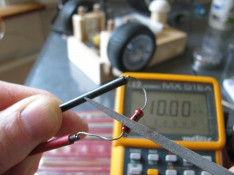
Here’s a tip to keep in your back pocket, you can use a metal file to adjust your resistors. [Gareth] shows off this technique in the video after the break. A metal file is literally all that you need to do some fine tuning. Just make sure you’re starting off with a carbon film resistor as this will not work with the metal film variety.

His example shows a 10k resistor which is reading just 9.92k on his multimeter. But he needs precisely 10k. After getting through the protective layer he makes just a couple of passes with a small file, each time adding about 20 Ohms of resistance. Now he does mention that excessive deep cuts can hurt the power rating of the resistor. But this certainly isn’t damaging it if done correctly. It turns out this is how they are tuned at the factory.

One possible use he mentions is trimming the balance on a hacked servo motor.

Continue reading “The Cool Kids All File Their Resistors For Accuracy”