We can say one thing for [bitluni]: the BOMs for his projects, like this ESP32 AM radio transmitter, are always on the low side. That’s because he leverages software to do jobs traditionally accomplished with hardware, always with instructive results.
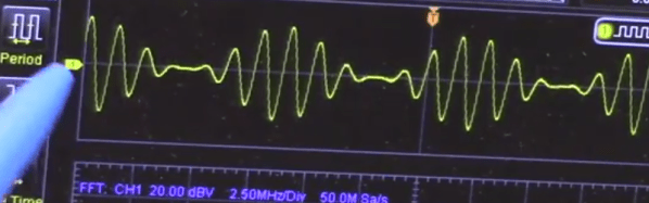
In this case, the job at hand is creating an RF oscillator in the broadcast AM band and modulating some audio onto it. From his previous experience using an ESP32 to watch video on an oscilloscope, [bitluni] knew that the microcontroller’s DACs were up to the task of producing an 800-kHz signal, and he managed to produce a more-or-less sine wave carrier with some clever code. His sketch takes data from a header file, modulates it onto the carrier, and sends it out over the ether using a short stub of wire for an antenna. The range is severely limited, but for what it is, it gets the job done and shows the basics. And as a bonus, [bitluni] included a bit of JavaScript that turns an audio file into a header file that’s ready to go out over the airwaves for all your trolling needs.
If you’re looking for a little more range for your low power transmitter and you’re a licensed amateur operator, you might want to explore the world of QRP radio.
Continue reading “ESP32 Makes For World’s Worst Radio Station”