Bitten By PCB Defects

If you’ve ordered PCBs from Seeed Studio, ITead, DirtyPCB, or another board house in China, you’ve probably noticed that neat little 100% e-test option available on the order form. If you select this, the board house will throw your PCBs in a machine that will poke a pin in every pad to make sure all the connections are good. Less work for you, right? As [Andy] found out, not always. He was bitten by a manufacturing defect that sheds some light on what that e-test actually is, and the capabilities of what these Chinese board houses can do.

Most of [Andy]’s project have a lot of surface mount components, and when he receives his boards, he notices a few pin pricks on each and every pad. This is from a flying lead machine; a robotic continuity checker that makes sure all the relevant pads are electrically isolated from each other.

One of [Andy]’s recent projects is an entirely through-hole design. Apparently these robotic meters don’t test through-hole pads; it’s significantly harder to measure the continuity of a hole rather than a pad, apparently. After assembling one of these boards, he noticed a problem where one of the GPIOs was permanently high. The offending trace was found underneath a DIP socket, in precisely the worst possible place it could be.

If [Andy] had inspected the board beforehand, this problem would have been avoided. He says it was a relatively simple board with big traces and wide spaces and he didn’t think a manufacturing defect was possible. He was wrong, and now we have a warning. We thank him for that.

Hackaday Prize Entry: A Better KVM Switch

Now it’s not uncommon to have a desktop and a laptop at a battlestation with tablets waiting in the wings. Add in a few Raspis, consoles, and various cheap computers, and it’s pretty easy to have an enormous number of machines and monitors on a desk. Traditionally, a KVM switch would be the solution to this, sharing a keyboard, mouse, and monitor with many different boxes, but this is an ugly solution. [frankstripod] has a device that fixes that with some interesting software and a few USB hacks.

[frankstripod] is in love with a program called Synergy this program combines the keyboard, mouse, and display of several computers over a network so you’ll only ever have to use one keyboard and mouse; it’s as simple as dragging your mouse from one computer to the other. There are a few limitations, though: keyboards don’t work until the OS has loaded (no BIOS access, then), it doesn’t work if the network is down, and setup can be complicated. This project aims to replace the ‘server’ part of a Synergy setup with a small, networkable KVM.

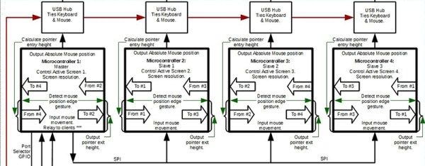
Right now the plan is to use a small embedded board running Linux to read a USB keyboard and switch the output between several computers. A few scripts detect the mouse moving from one screen to another, and a microcontroller switches USB output between each computer. If it sounds weird, you’re right, but it does work: [frank]’s 2014 Hackaday Prize project was a mouse that worked with two computers at once.


The 2015 Hackaday Prize is sponsored by:

Pinball Simulator Makes The Neighbors Happy

There are a lot of simulators out there if you want to try something out that would be otherwise impossible. Great examples are flight simulators for simulating the piloting of a fighter jet, or goat simulators for simulating the life of a goat who destroys a town. [Erland] wanted a pinball machine, but like planes and goats, found it was impractical to get a real one because it would probably upset his neighbors in his apartment. Instead, he set out to build a pinball simulator.

The cabinet is miniature-sized compared to a regular pinball machine so it can more easily fit in the apartment. It utilizes three monitors, a 24″ one in portrait mode for the main playing area, a 20″ one for the back screen, and a smaller one for the “dot matrix” style scoreboard. Once the woodwork was completed, a PC was put together to control everything and an Arduino was installed to handle the buttons and output USB commands to the PC.

Of course, we’ve featured many other pinball simulators before, but this one is no slouch when it comes to features either. It is very well crafted and the project is very well documented, and the miniature size sets it apart as well. However, if you want to go a step further with your pinball simulator, you might want to check out this augmented reality pinball system.

TechCrunch Disrupt: Charging A Phone With Its Own Transmitter

TechCrunch Disrupt is on this week, and that means we get to see which members of tech media don’t understand basic physics. So far, it’s writers from Engadget, The Mirror, Business Insider, TechCrunch, and four judges on the TC Disrupt stage. What is the consequence of not understanding the implications of the conservation of energy? Glowing support for a cell phone that can charge itself.

The offending Disrupt startup is Nikola Labs, and they’re gearing up to launch a Kickstarter for a very special iPhone 6 case. This case uses small, energy-harvesting antennas to gather RF energy from the cellphone tucked away in this case. This energy is then sent to a rectifier where it is converted into something the Apple Lightning connector can sip power from. According to Nikola Labs, this RF harvesting antenna takes energy from the transmissions of the iPhone 6 entombed in this case, converts it to about 5 Volts, and uses that to charge the iPhone battery.

I know that seems difficult to understand, so here’s a simple analogy: you have a flashlight with a battery and a solar cell. The solar cell recharges the battery. If this were a Nikola Labs flashlight, you would recharge it by shining the flashlight onto the solar cell.

That is the simplest explanation of what the Nikola Labs cellphone case does, and illuminates the limitations of what it can do. If the ‘energy harvesting circuit’ collects power from the device it is recharging, it will reduce the transmission power of whatever is transmitting. With the cellphone case, you’re spending transmission power (plus efficiency losses) to recharge the battery. That means poorer reception and fewer bars. In the solar-recharging flashlight analogy, the flashlight would either be dimmer, or you could only use it part of the time.

It’s also why Nikola Labs claims their case will only recover 30% of the battery life of an iPhone 6; the battery isn’t solely dedicated to a transmitter – there’s a display and a CPU to account for in the power budget.

To Nikola Labs’ credit, this is at least a novel application of the RF energy harvesting trope that has been making its way around Kickstarter and tech blogs for a few years. Nearly every other RF harvesting idea that has been pitched in recent memory decouples the transmitter (or ‘generator’, I guess) with the product or receiver. The square cube law is an evil mistress, and if you’re wondering why these devices don’t work, [ch00f], a guy with an actual engineering degree, has a great writeup of one of these products over on Drop Kicker.

The Nikola Labs cellphone case bucks this trend by looking at the shortcomings of these devices; an RF rechargeable Bluetooth tag won’t work if you place it a foot away from a WiFi router, but it just might if you tape it to the antenna. This is the idea behind Nikola Labs’ invention: harvest energy from a few millimeters away from the cell phone’s antenna. According to Nikola Labs, their engineer, [Chi-Chih Chen] has a patent in the works for this. This patent application has not been published yet.

In theory, the Nikola Labs cellphone case will actually recharge your battery, but at a price: you’d be wasting your transmission power on recharging the battery. It’s a false economy that you’ll be able to fund on Kickstarter next month for $100 USD. If you’re only looking for more battery life, walk into any gas station, buy a $10 USB power bank/battery, and have enough portable power to recharge your iPhone battery to 100%. That’s not a sexy solution, it doesn’t reference [Nikola Tesla], and it’s not snake oil that tech media is lapping up like dogs. Pity.

Retrotechtacular: The Spirit Of Radio

Many of us still tune in to terrestrial radio for one reason or another, be it baseball games, talk radio, or classic rock. But do you know how the sound is transmitted to your receiver? This week, our spotlight shines upon a short film produced by KYW Radio that serves as a cheerful introduction to the mysteries of amplitude modulation (AM) radio transmission as they were in 1940.

Sound vibrations enter a microphone and are converted to electrical current, or an audio waveform. The wave is amplified and sent several miles away to the transmitting station. During this trip, the signal loses power and so is amplified at the transmitting station in several stages. This audio wave can’t be transmitted by itself, though; it needs to catch a ride on a high-frequency carrier wave. This wave is generated on-site with a huge crystal oscillator, then subjected to its own series of amplifications prior to broadcast.

The final step is the amplitude modulation itself. Here, the changing amplitude of the original audio wave is used to modulate that of the high-frequency carrier wave. Now the signal is ready to be sent to the tower. Any receiver tuned in to the carrier frequency and in range of the signal will capture the carrier wave. Within the reciever, these currents are converted back to the vibrations that our ears know and love.

Continue reading “Retrotechtacular: The Spirit Of Radio”

[Kenji Larsen] Shows Off The Ultimate Hacking Kit

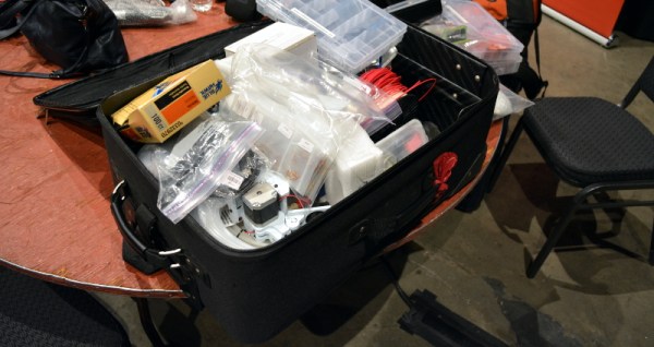
If you roll into a hardware hackathon empty-handed, you’re going to be at a disadvantage compared to those who bring equipment with which they’re already familiar. Pray that you never roll into one where [Kenji Larsen] is your competitor. Luckily, this weekend he came out to mentor for Hackaday’s hardware hacking village at the TechCrunch Disrupt hackathon and not as a competitor. In this video he shows off the huge rollerbag which he calls his “Hack Pack”. I’d say there’s a 50/50 chance his travel setup is better than your home lab.

Where do I begin (seriously, watch the video)? Perhaps best to note is how organized he is. For instance, the large plastic bag containing his battery-operated and plug-in Dremels also has conveniently sized stock like acrylic and metal. There are compartment boxes full of sensors, others contain things like passives, batteries, battery chargers, hundreds of Moteino modules, handfuls of BeagleBones Black, breakout and dev boards of every flavor. He has all the necessary tools like hemostat, x-acto blade, steel ruler, and magnifying glasses. There’s even a 3D printer in the bag — a Printrbot Simple which [Chris Gammell] played with all weekend err… learned to use as part of his role as a mentor.

We had a ton of hardware along with us, but time and again [Kenji] was there for the save on some of the less-common needs. He’s a expert when it comes to fabrication techniques and it showed. We also give him mad points for staying up overnight for all 20-hours of the build session. Thank you so much [Kenji], I think I speak for every one of the hardware hackers when I say you helped bring the event to the next level of exhilarating and exhausting fun. Please direct your own thanks, stories, and well-wishes, and follows to [Kenji’s] hacker profile.

If you weren’t able to make it to NYC this weekend, you definitely missed out. We’ll be telling the story of that all week. Those on the West Coast will have a chance next weekend at Hackaday Prize Worldwide: LA. The workshop is sold out but socializing on Saturday, and a Sunday free-build are both still available for RSVPs.

Open Source, DIY Soldering Robot

After [Brian] starting selling his own Raspberry Pi expansion boards, he found himself with a need for a robot that could solder 40-pin headers for him. He first did what most people might do by looking up pre-built solutions. Unfortunately everything he found was either too slow, too big, or cost as much as a new car. That’s when he decided to just build his own soldering robot.

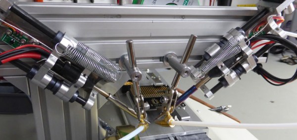
The robot looks similar to many 3D printer designs we’ve seen in the past, with several adjustments. The PCBs get mounted to a flat piece of aluminum dubbed the “PCB caddy”. The PCBs are mounted with custom-made pins that thread into the caddy. Once the PCBs are in place, they are clamped down with another small piece of aluminum. A computer slowly moves the caddy in one direction, moving the header’s pins along the path of the soldering irons one row at a time.

The machine has two soldering irons attached, allowing for two pins to be soldered simultaneously. The irons are retracted as the PCB caddy slides into place. They irons are then lowered onto the pins to apply heat. Two extruders then push the perfect amount of solder onto each pin. The solder melts upon contact with the hot pins, just as it would when soldered by hand.

The system was originally designed to be run on a Windows 8.1 tablet computer, but [Brian] found that the system’s internal battery would not charge while also acting like a USB host. Instead, they are running the Windows WPF application on full PC. All of the software and CAD files can be found on [Brian’s] github page. Also be sure to check out the demo video below. Continue reading “Open Source, DIY Soldering Robot”