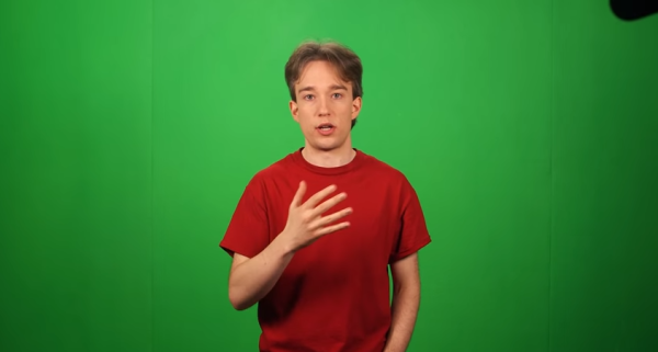
Build An Audio Spectrum Analyzer The Analog Way

bandpass

[Ryan] wanted a spectrum analyzer for his audio equipment. Rather than grab a micro, he did it the analog way. [Ryan] designed  a 10 band audio spectrum analyzer. This means that he needs 10 band-pass filters. As the name implies, a band-pass filter will only allow signals with frequency of a selected band to pass. Signals with frequency above or below the filter’s passband will be attenuated. The band-pass itself is constructed from a high pass and a low pass filter. [Ryan] used simple resistor capacitor (RC) filters to implement his design.

All those discrete components would quickly attenuate [Ryan’s] input signal, so each stage uses two op-amps. The first stage is a buffer for each band. The second op-amp, located after the band-pass filters, is configured as a non-inverting amplifier. These amplifiers boost the individual band signals before they leave the board. [Ryan] even added an “energy filler” mode. In normal mode, the analyzer’s output will exactly follow the input signal. In “energy filler” (AKA peak detect) mode, the output will display the signal peaks,  with a slow decay down to the input signal. The energy filler mode is created by using an n-channel FET to store charge in an electrolytic capacitor.

Have we mentioned that for 10 bands, all this circuitry had to be built 10 times? Not to mention input buffering circuitry. With all this done, [Ryan] still has to build the output portion of the analyzer: 160 blue LEDs and their associated drive circuitry. Going “all analog” may seem crazy in this day and age of high-speed micro controllers and FFTs, but the simple fact is that these circuits work, and work well. The only thing to fear is perf board solder shorts. We think debugging those is half the fun.

SMAC Mag: Spider’s Minimal Analog Control Paintball Gun

paintballsmac

[Spider!]’s contribution to the pantheon of paintball markers is the SMAC: a unique revision to one of Airgun Design’s ever-popular Automags. We needed our tipster, [Russell] to provide some context on the Automag’s evolution, because the brand has served as a popular hacking platform for nearly 20 years. The most frequent is a “Pneumag” modification, which converts the original, fully-mechanical trigger pull into a version where the trigger actuates a pneumatic cylinder to fire the gun.

According to [Russell], the Pneumag’s trigger must completely release between each shot to properly recharge the firing chamber. Without a full release, the gun can load extra balls into the barrel and lead to gloppy consequences. Electronic controls solve this problem, but [Spider!] favored an analog solution that captured a “less is more” mentality over a pre-fab microcontroller board. He built the circuit around a 556 timer used as a delayed re-trigger, but with a few modifications.

Swing by [Spider!]’s forum post for additional details, a cluster of pictures and a bill of materials. Microcontroller alternatives? We’ve got you covered.

Analog Drum Machine

Drum Machine Schematic

This analog drum machine project synthesizes a kick and snare drum that are clocked to a beat. It pulls together a few analog circuits to do the timing and synthesis.

The beat timing is a product of a hysteretic oscillator used to create a ‘shark wave,’ which is a friendly term for the output of a relaxation oscillator. This waveform can be compared to a set point using a comparator to create a slow square wave that clocks the drum beat.

The kick drum is synthesized using another hysteretic oscillator, but at a higher frequency, creating a triangle-like waveform at 265 Hz that provides a bass sound. The snare, however, uses white noise provided by a BJT’s P-N junction, which is reverse biased and then amplified. You can spot this transistor because its collector is not connected.

The resulting snare and kick drum wave forms are gated by two transistors into the output. Controlling these gates allows the user to create a drum beat. After the break, check out a video walk-through and a demo of the build.

Continue reading “Analog Drum Machine”

Digitally Controlled Dual Power Supply

[Kerry] set out to build a digitally controlled dual supply for his bench. He’s already built a supply based on the LM338 linear regulator, but the goal this time was to build it without a linear regulator IC, and add digital control over both the current and voltage.

In part one of the build, [Kerry] explains the analog design of the device. He had an extra heatsink kicking around, which can dissipate enough heat from this linear supply to let it run at 10 A. A NE5532 opamp is used to track a reference voltage, which can be provided by a DAC. The current is measured by a LT6105 shunt sense amplifier, then compared to a reference provided by another DAC.

Part two focuses on the digital components. To interface with the analog circuitry, two MCP4821 DACs are used. These are controlled over SPI by an ATmega328P.

Fortunately, [Kerry] also has his own DC load project to test the supply with.

Rebuilding A 1940s TV

TV

There’s a lot of cool stuff to be found under piles of trash in an antique store. [dijt] discovered this when he found a tiny 7″ Motorola television from the 1940s under a stack of trinkets from earlier eras. We can understand [dijt]’s impulse buy, and the trials of rebuilding this ancient TV more than qualifies it as a hack.

If you know where to look, there are hundreds of resources available for old televisions, Hi-Fis, and radio equipment from the dawn of the electrical era to the modern day. After consulting with a few forums, [dijt] got his hands on a schematic for his television set and began work on diagnosing what was wrong with it.

It turned out the original ballast tube in this set had long since given up the ghost. Luckily, this is a common problem in old TVs, and after consulting some forums [dijt] had a schematic to replace this ballast tube with some newer caps and resistors.

After constructing the circuit and testing it out, [dijt] mounted it in the old ballast tube to replicate the original look and feel of the 1949 television. Interestingly, this is the second time this TV had been restored; the 1960s-era caps and resistors told [djit] this TV had once went into a television repair shop. Let’s just hope [djit] remembered to glue the schematics to the inside of the chassis this time.

Avalanche Pulse Generator Design

avalanche-pulse-generator

This avalanche pulse generator is a great way to test your mettle as an Electronics Engineer. The challenge is to truly understand how each part of the design works. We certainly got a failing grade when first studying the schematics more than a week ago. But we’re slowly beginning to understand what’s going on under the hood.

The concept of an avalanche transistor is some wicked voodoo from the analog side of the street which leverages a transistor’s breakdown voltage to achieve a predictable result. In laymen’s terms it (mis)uses a transistor to produce a really fast pulse. The write-up linked above references several previous avalanche pulse generator designs, but this one is a bit different in how it produces about 50V from a pair of AAA batteries using a multivibrator circuit.

Even if you have no idea what’s going on here you may be interested in the last few paragraphs where the circuit is measured using a cutting-edge Teledyne LeCroy Wavemaster 820Zi-A. That’s a 20 GHz scope with a 15.3″ screen which you’ll never ever own.

Crystal Oven Temperature Sensor Reads 0.01F Resolution

crystal-oven-temperature-sensor

[Scott Harden] continues his work on a high precision crystal oven. Being able to set a precise temperature depends on the ability to measure temperature with precision as well. That’s where this circuit comes in. It’s based around an LM335 linear temperature sensor. He’s designed support circuitry that can read temperature with hundredth-of-a-degree resolution.

Reading the sensor directly with an AVR microcontroller’s Analog-to-Digital Converter (ADC) will only yield about 1-2 degrees of range. He approached the problem by amplifying the output of the sensor to target a specific range. For the demonstration he adjusts the swing from 0-5V to correspond to a room temperature to body temperature range.

Of course he’s using analog circuitry to make this happen. But before our digital-only readers click away you should view his video explanation. This exhibits the base functionality of OpAmps. And we think [Scott] did a great job of presenting the concepts by providing a clear and readable schematic and explaining each part slowly and completely.

So what’s this crystal oven we mentioned? It’s a radio project that goes back several years.

Continue reading “Crystal Oven Temperature Sensor Reads 0.01F Resolution”