The last thing an astronaut or cosmonaut on the International Space Stations wants to hear from one of their crewmates is, “Do you smell plastic burning?” But that’s apparently what happened this week aboard the increasingly problematic spacecraft, as the burning smell and visible smoke spread from the Russian Zvezda module to the American side of town. The reports say it occurred while charging the station’s batteries, and we all know how dicey that can get. But apparently, the situation resolved itself somehow, as normal operations continued soon after the event. Between reports of cracks, air leaks, problems with attitude control, and even accusations of sabotage, the ISS is really starting to show its age.
Speaking of burning and batteries, normally a story about burning Tesla batteries wouldn’t raise our eyebrows much. But this story out of California introduces a potential failure mode for Tesla batteries that we hadn’t considered before. It seems a semi-truck with a load of Tesla batteries lost its brakes on Interstate 80 in the Sierra Nevada mountains and ended up flipping across the highway. Video from the scene shows the cargo, which looks like replacement batteries or perhaps batteries salvaged from wrecked cars, scattered across the highway on their shipping pallets. A fire was reported, but it’s not clear whether it was one of the batteries which had gotten compromised in the crash, or if it was something other than the batteries. Still, we hadn’t considered the potential for disaster while shipping batteries like that.
Attention all GNURadio fans — GRCon21 is rapidly approaching. Unlike most of the conferences over the last year and half, GRCon21 will actually be both live and online. We always love the post-conference dump of talks, which cover such a wide range of topics and really dive deeply into so many cool areas. We’re especially looking forward to the SETI talks, and we’re pleased to see our friend Hash, who was on the Hack Chat a while back, scheduled to talk about his smart-meter hacking efforts. The conference starts on September 20 and is being held in Charlotte, North Carolina, and virtually of course. If you attend, make sure to drop tips to your favorite talks in the tips line so we can share them with everyone.
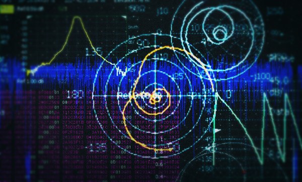
We got a tip this week on a video about how 1/4-wave tuning stubs work. It’s a simple demonstration using a length of coax, a signal generator, and an oscilloscope to show how an unterminated feedline can reflect RF back to the transmitter, and how that can be used to build super-simple notch filters and impedance transformers. We love demos that make the mysteries of RF a little simpler — W2AEW’s videos come to mind, like this one on standing waves.