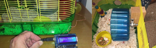
The Arduino has inspired many a creative projects that can be beneficial to humanity. The Arduino Hamster Wheel Pedometer by [John Mueller] on the other hand is a creation that is meant for the cute furry rodent pets. When [John Mueller]’s daughter wanted to keep track of her hamster’s night-time strolls, her maker-dad saw it as an opportunity to get her involved in technology. The project consists of a hamster-wheel with a magnet that triggers a reed switch on completing a revolution. The entire assembly is custom-made and [John Mueller] does an excellent job documenting the build with a lot of clear images.
The wheel is affixed to a shaft with a ball bearing at one end and the entire thing is mounted on the side of the cage so that it can be removed with ease for maintenance. The reed switch is embedded in the wooden mounting block such that the connecting cables pass from inside the assembly. This prevents the hamster from coming in contact with the cabling or damaging it in any way. An LCD and the Arduino Uno are placed outside the cage and are used to display the revolutions of the wheel as well as the equivalent miles travelled.
The code for the Arduino is also supplied for anyone who wants to replicate the project and the video below shows the working of the project. The project could also be extended to count calories burned as well as running speed. This project is a prime example of how technology can be used to assist and is similar to the IoT Hamster Wheels that tweets every movement of the Hamster Life.
Continue reading “Pedometer For Calorie Conscious Hamster Owners”


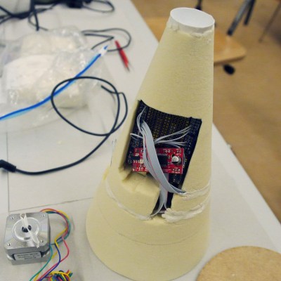 The project consists of an Arduino connected to a color sensor as well as a SparkFun EasyDriver. The EasyDriver controls a stepper motor which rotates a disc of scent swatches so you sniff the swatch corresponding with the color. The students chose strawberry for red, and blue ended up being “ocean”-scented room spray.