Ice Tube Clock, Meet The ChronoDot

[Alex] ramped up the precision of his timepiece by adding a ChronoDot to the Ice Tube Clock. These two items are among our favorites; the Ice Tube Clock for its old-style multi-digit display, and the ChronoDot for combining a DS3231, battery, and components into a nice small package.

There is a schematic link at the very bottom left of [Alex’s] writeup. He mentions that he depopulated the clock crystal and its capacitor pair from the board and patched into the clock input on the AVR. A 100K pull-up resistor is included in the wiring as called for in the DS3231 datasheet. Although not specifically referenced, we assume that [Alex] reprogrammed the ATmega168 clock select fuses to use an external clock signal.

Now he can sit back knowing that the clock will be within 10 seconds per year accuracy.

AVR Programming 04: Writing Code, Etc.

Welcome back to this fourth and final installment of the series. The first three parts should have been enough to get you off the ground, but a few more learning examples wouldn’t hurt. It’s also a good time to discuss some of the other things these little chips can do. Join me after the break to:

  • Expand the sample code, adding features to our simple program while I challenge you to write the code yourself.
  • Discuss AVR fuse bits, how to use them, and what to watch out for
  • Touch on some of the peripherals you’ll come across in these chips

As a grand flourish to the series, I’ve used the example hardware from this final part to build a bicycle tail light. Hopefully this will inspire you to create something much more clever.

Series roadmap:

Continue reading “AVR Programming 04: Writing Code, Etc.”

AVR Controlled RGB LED Matrix Plays Tetris

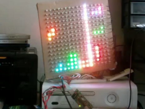
[Stan] built this LED matrix using a 16×16 grid of RGB LEDs. He built the hardware and wrote some subroutines to randomize the colors. He’s not using PWM because frame buffering is not feasible for the 1k SRAM limit of the ATmega168 he used. Instead, shift registers drive the lights which can be mixed to achieve eight different colors (including off for black) reducing the framebuffer size to just 96 bytes. After he got done with the build he realized this is sized well for a game of Tetris. We’ve seen AVR tetris, PIC Tetris, and Tetris using composite video but it’s always a pleasure to see a new display build.

After the break we’ve embedded [Stan’s] demo video, several pictures, and a schematic. He’s using many of the same principles outlined in our How to Design an LED matrix tutorial.

Continue reading “AVR Controlled RGB LED Matrix Plays Tetris”

70 LED Matrix In A Jack-o-lantern

What takes eight hours to solder and uses more shrink tubing that you thought imaginable? An LED matrix installed in a real pumpkin. When I mentioned that we’d like the LED pumpkin in last Friday’s post scaled up to a full LED matrix I had no idea it would be me doing the work. But [Caleb] and I thought it might be just the thing to present for the hacker’s favorite holiday.

Installed in the autumn vegetable is a marquee made from a 5×14 matrix of light emitting diodes. I spaced them by printing out a grid on the computer, taping it to the pumpkin, and drilling 70 holes in the front of the thing. The real trouble came when inserting all of the LEDs from the inside; each of them has four wires soldered to it, creating a net of black wiring. Above you can see it turned out great. This is a shot of it scrolling the message HAPPY HALLOWEEN.

Join us after the break for video of this prop. But we’re not just sharing the finished product. I’ll take you through the build process. Along the way you’ll learn the design considerations that go into an LED matrix and how you can use these techniques to build your own in any size and configuration you desire.

Continue reading “70 LED Matrix In A Jack-o-lantern”

AVR Programming 02: The Hardware

You may be able to write the most eloquent code in the history of embedded systems but without a way to run it on the hardware it will be worthless. In this installment of the tutorial series we will:

  • Look at some of the available AVR programmer options
  • Place the microcontroller on a breadboard and connect it to a power supply and a programmer.
  • Use programming software to send some example code to the microcontroller

If you missed Part 1 take a few minutes to review that portion of the tutorial and then join us after the break.

Series roadmap:

Continue reading “AVR Programming 02: The Hardware”

Full-featured AVR Time-lapse

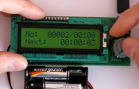
This time-lapse photo trigger was built [Lukasz Goralczyk]. It is controlled by an ATmega168 and we were surprised to read that it uses about 12k of code. Curious about what takes up that much space, we were impressed to see all the features demonstrated in the video after the break. The small device, running on two AA batteries, has a well-designed user interface displayed on a 3V character LCD that is navigated with a clickable rotary encoder.

It isn’t the smallest intervalometer we’ve ever seen, but it deserves respect for the features packed into a diminutive form-factor.

Continue reading “Full-featured AVR Time-lapse”

Matrix Clock Is A Breadboarding Win

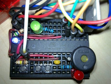
Normally when we feature a clock made with a 32×8 LED matrix we’d load up an image of the display for the banner photo. But this time around we were so impressed by [JB’s] breadboard work we had to use this image. We see an ATmega168, three buttons, three LEDs, a piezo buzzer, 32.768 kHz crystal, smoothing capacitor, and a few resistors; everything he needed to keep time and display it on the matrix module. If this is just going to sit on your bookshelf for a while it’s a great alternative to point-to-point soldering on a protoboard. Nice work fitting it all on there [JB].