Meet The New Moteus BLDC Controller Board, The N1

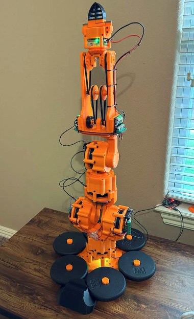
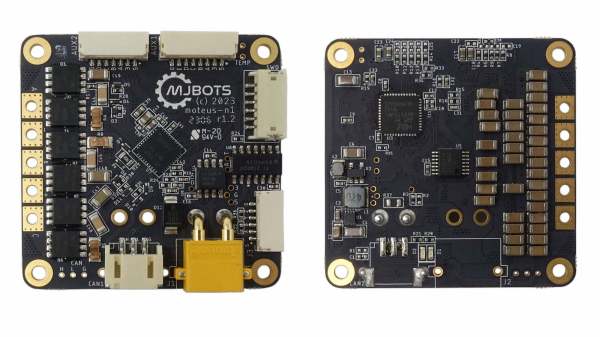
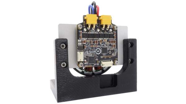
[Josh] over at mjbots just released a new version of the moteus controller board, dubbed the moteus-n1. One change is that the volume and footprint size has been reduced. Considering many people, [Josh] included, use these controllers to operate robotic dogs, smaller is better. The previous moteus controller maxed out at 44 V, but the n1 can run at up to 54 V, allowing use of 48 V power supplies. And [Josh] improved the interface circuitry, making it much more flexible than before. This comes at an increased price, but he sells both versions — parts availability permitting. And like the previous versions of the moteus controller, this is an open source project and you’re free to build it yourself. You can check out the complete design package at the project’s GitHub repository.

One helpful point is that the firmware for the n1 is the same, it simply enables new features related to the I/O ports. This means a user could swap in a new controller with no impact to their system. Maintaining firmware compatibility was just one of the challenges [Josh] faced along the way. Squeezing additional functionality into the small number of user-exposed I/O pins was a chore, but dealing with supply chain issues was a big headache:

…make a revision that leveraged the parts I had, along with ensuring that the parts I needed were achievable to purchase in a reasonable time frame. Some parts orders for this batch were placed nearly a year ago.

Check out moteus if you need a brushless servo controller. We covered the previous major upgrade last year, which was primarily firmware and interface focused.

Photograph of a BLDC motor controller circuit board

Take A Ride Through The Development Of A Custom BLDC Motor Controller

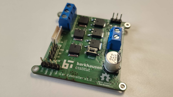
The folks over at the [Barkhausen Institut] are doing research into controlling autonomous fleets of RC cars and had been using off the shelf electronic speed controllers (ESCs) to control the car motors. Unfortunately they required more reliable feedback for closed loop control of the motors, so they created their own open source hardware brushless DC (BLDC) controller.

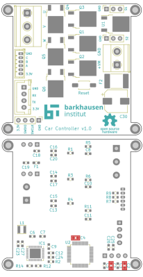
The motor controller they developed uses an STM32 microcontroller that talks to a TMC6140 3 phase MOSFET driver to drive 6 IRLR 2905 MOSFETs. The [Barkhausen Institut] researchers went with the SimpleFOC library as the basis to program the STM32, with installed hall effect sensors indicating motor orientation for their closed loop control.

Designing a functioning BLDC and ESC controllers can be subtle, and their post goes into details about the problems and solutions they came up with to deal with with what was ultimately improper isolation of the MOSFETs interfering with the power rail for the STM32. The source for their BLDC motor controller is available through their GitLab page. For more information on the parent project that uses the BLDC driver, be sure to check out their work on a connected convoy of RC cars.

There’s now a wealth of open source BLDC drivers and projects, many of which we’ve featured in the past, like the Moteus and haptic smart knob, and it’s nice to see other projects explore different options.

Moteus Open Source BLDC Controller Gets Major Upgrade

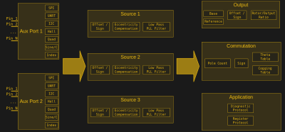
[Josh Pieper] of mjbots Robotic Systems just released a major revision to his moteus open sourced brushless DC (BLDC) electric motor controller. The update adds a flexible I/O subsystem which significantly expands the kinds of feedback encoders and peripherals the controller can accept. In the video below the break, [Josh] walks through eleven different example configurations. If you prefer, these examples are also presented in article form on his blog.

The moteus controller originally came about when [Josh] was developing the quad A0, an open source dynamic quadruped robot, along the lines of the MIT Mini Cheetah or Boston Dynamics robotic dogs, and wasn’t satisfied that existing controllers could do the trick. It’s a compact 50 mm square board based on an STM32G4, has an integrated magnetic encoder, and accepts external sensor connections. Interfacing with the board is via CAN-FD using a register-based scheme. A Python GUI tool provides name-based register access via a logical tree structure as well as real-time telemetry plotting capabilities for diagnostic and configuration tasks.

If you are using BLDC motors in your projects, definitely check this out. Even if you’re not using a moteus controller, [Josh]’s demonstrations of the various encoder feedback technologies is very interesting and educational. The entire project is open source, and both the hardware and software design files can be found on the project’s GitHub repository. For some users, this may be a major factor, considering that the latest ODrive BLDC controller offering has become closed source.

We wrote about the mjbots quad A0 in 2019, and you can follow the moteus project over on Hackaday.io. We also found this interesting video by [Skyentific] comparing three popular open source BLCD controllers including the moteus (second video below the break). There’s also the SimpleFOC project we covered last year if you want to dig in and learn more about field-oriented control of BLDC motors. Thanks to [Androiddrew] for the tip.

Continue reading “Moteus Open Source BLDC Controller Gets Major Upgrade”

Ball Balancing Wheel Puts A Spin On Inverted Pendulums

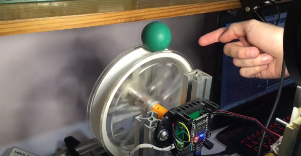
If you march sufficiently deep into the wilderness of control theory, you’ll no doubt encounter the inverted pendulum problem. These balancing acts have emerged with a number of variants over the years, but just because it’s been done before doesn’t mean there’s no space for something new. Here, [David Gonzalez], has taken this classic problem and given it an original own spin–literally–where the balancing act is now a ball balanced precariously upon a spinning wheel. (Video, embedded below.) Mix in a little computer vision for sensing, a dash of brushless motor control, a bit of math, and you have yourself a closed-loop system that’s bound to turn a few heads.

[David’s] implementation is a healthy mix of classic control theory with some modern electronics. From the theory bucket, there’s a state-space controller to drive both the angle and angular velocity of the ball to zero. The “state” is a combination of four terms: the ball angle, the ball’s angular velocity, the wheel angle, and the wheel’s angular velocity. [David] weights each of these terms and sums them together to create an input value to adjust the motor velocity driving the wheel and balance the ball.

From the electronics bin, [David] opted for an ESP32 running Arduino, the custom Janus Brushless Motor Controller running SimpleFOC, and a Maix Bit Microcontroller with an added camera running MicroPython to compute the ball angle. Finally, if you’re curious to dig into the source code, [David] has kindly posted the firmware on Github.

We love seeing folks mix a bit of control theory into an amalgamation of familiar electronics. And as both precision sensors and motor controllers continue to improve, we’re excited to see how the landscape of projects changes yet again. Hungry for more folks closing the loop on unstable systems? Look no further than [UFactory’s] ball balancing robot and [Gear Down for What’s] two wheeled speedster.

Continue reading “Ball Balancing Wheel Puts A Spin On Inverted Pendulums”

Custom Controller Makes Turbomolecular Pump Suck

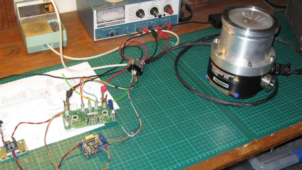
[Mark Aren] purchased a pair of Turbomolecular pumps (TMP) sans controllers, and then built an FPGA based BLDC controller for the Turbomolecular pumps. A TMP is similar to a jet turbine, consisting of several stages of alternating moving turbine blades and stationary stator blades, and having turbine rotation speeds ranging from 10,000 rpm to 90,000 rpm. TMP’s cannot exhaust directly to atmosphere, and must be combined with a backing (or roughing) pump to create a lower grade vacuum first. They find use in lots of applications such as electron microscopy, analytical sciences, semiconductors and lamp manufacturing. With the lamp industry rapidly embracing LEDs, many of the traditional lamp making lines are getting decommissioned, and if you are lucky, you can snag a TMP at a low cost – but it still will not be cheap by any means.

The two BOC-Edwards EXT255H Compound Molecular Pumps (PDF), that [Mark] bought did not have their accompanying EXC100E Turbomolecular Pump Controllers (PDF), and given pandemic related restrictions, he decided to build a controller of his own, using components and modules from his parts bin. The pump and controller user manuals offered only sketchy details about the sensored BLDC motor used in the pump. The low phase-to-phase resistance implied low drive voltage, and [Mark] decided to try running it at 24 V to start with. He already had experience using the Mitsubishi PS21245-E IGBT inverter bridge, and even though it was rated for much higher voltages, he knew that it would work just fine at 24 V too.

After figuring out a state machine for motor commutation that utilized PWM based adjustable current control, he implemented it on a 128 element FPGA board. Considering how expensive the TMP was, he wisely decided to first try out his driver on a smaller “expendable” BLDC motor. This whole process was non-trivial, since his available IGBT module was untested and undocumented, and required several tweaks before he could run it at the required 12 kHz PWM signals. His test motor was also undocumented, failing to run correctly when first hooked up. Fixing that issue meant having to disassemble the motor to check its internal wiring. Eventually, his efforts paid off, and he was able to safely run the TMP motor to confirm that his design worked.
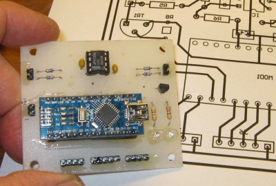
With FPGA code, IGBT wiring and power supply issues sorted, the next step was to add a supervisory micro-controller, using an Arduino Nano. Its functions included interfacing with a touch screen LCD as a user interface, communicating with the FPGA module, and controlling several relays to switch power to the motor power supply, the roughing pump, TMP cooling fan, and a solenoid for the vacuum vent. Spindle current is calculated by measuring voltage drop across shunt resistors on the low side of the IGBT. Motor speed is measured using one of the motor hall sensors, and a thermistor provides motor temperature sensing. [Mark]’s PCB fabrication technique seems a bit different too. Using an Excellon drill file, he drills holes in a piece of plastic using a laser cutter to create a bare board, and then solders copper tracks by hand.

His initial tests at atmospheric pressure (although not recommended unless you monitor pump temperature), resulted in 7300 rpm while consuming about 7 Amps before he had to shut it down. In further tests, after adding a roughing pump to the test setup, he was able to spin the TMP to 20,000 rpm while it consumed 0.6 A. Obviously, the pump is rated to operate at a higher voltage, possibly 48 V based on the values mentioned in the TMP controller manual. The project is still “work in progress” as [Mark] hopes to eventually drive the pump up to its specified 60,000 rpm operating speed. What is not clear is what he eventually intends to do with this piece of exotic machinery. All he mentions is that “he has recently taken an interest in high-vacuum systems and is interested in exploring the high-vacuum world of electron guns.”

Maybe [Mark] can compare notes with the Open Source Turbomolecular Pump Controller that we featured some time back. And if you’d like to be a little bit more adventurous and build you own TMP, we got you covered with this DIY Everyman’s Turbomolecular Pump.

A Pet Robot, Just Like Boston Dynamics Makes

Every few months or so, a new video from Boston Dynamics will make the rounds on the Internet. This is their advertising, because unless the military starts buying mechanical mules, Boston Dynamics is going to be out of business pretty soon. You’ll see robots being kicked down the stairs, robots walking through doors, and robots acting like dogs. If a hundred or so highly skilled and highly educated roboticists, technologists, and other experts can put together a walking dog robot in a decade, obviously one person can cut through the cruft and build one in a basement. That’s what [Misha] is doing. It’s the Dizzy Wolf, a robotic wolf, or dog, or cat, we don’t actually know because there’s no fur (or head) yet. But it is interesting.

The key component for any quadruped robot is a high-torque, low-noise servo motor. This isn’t a regular ‘ol brushless motor, and for this application nine gram servos go in the trash. This means custom made motors, or DizzyMotors. You’re looking at a big brushless motor with a planetary gearset, all squished into something that could actually fit into the joint of a robotic wolf’s leg.

There’s a driver for these motors, strangely not called the DizzyDriver, that turns a BLDC into a direct drive servo motor. It is effectively a smart servo, that will move to a specific rotation, receive commands over RS-485, and write back the angular position. It also applies constant torque. Of course, there is a video of the DizzyMotor and servo driver below.

Building a robotic dog that will walk around the house is one of the hardest engineering challenges out there. You’ve got fairly crazy kinematics, you’ll need to think about the strength of the frame, control systems, and eventually how to fit everything in a compact design. This project is hitting all the marks, and we can’t wait to see the Dizzy Wolf do a backflip or chase a ball.

Continue reading “A Pet Robot, Just Like Boston Dynamics Makes”

Completely Scratch-Built Electronic Speed Controller

Driving a brushless motor requires a particular sequence. For the best result, you need to close the loop so your circuit can apply the right sequence at the right time. You can figure out the timing using a somewhat complex circuit and monitoring the electrical behavior of the motor coils. Or you can use sensors to detect the motor’s position. Many motors have the sensors built in and [Electronoobs] shows how to drive one of these motors in a recent video that you can watch below. If you want to know about using the motor’s coils as sensors, he did a video on that topic, earlier.

The motor in question was pulled from an optical drive and has three hall effect sensors onboard. Having these sensors simplifies the drive electronics considerably.

Continue reading “Completely Scratch-Built Electronic Speed Controller”