A Buck-Boost Converter From The Ground Up

DC to DC conversion has come a long way. What was once took an electromechanical vibrator and transformer has been reduced to a PC board the size of a largish postage stamp that can be had for a couple of bucks on eBay. So why roll your own buck-boost converter for the ground up? Maybe because sometimes the best way to learn is by doing.

Continue reading “A Buck-Boost Converter From The Ground Up”

How Does A Buck Converter Work Anyway?

[Great Scott] should win an award for quickest explanation of a buck converter. Clocking in at five and a half minutes, the video clearly shows the operating principles behind the device.

It starts off with the question, what should you do if you want to drop a voltage? Many of us know that we can dim and brighten an LED using the PWM on an Arduino, but a closer inspection with an oscilloscope still shows 5V peaks that would be dangerous to a 3.3V circuit. He then adds an inductor and diode, this keeps the current from dropping too fast, but the PWM just isn’t switching fast enough to keep the coil energized.

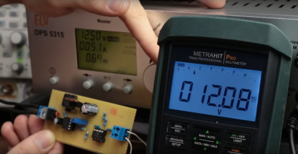
A small modification to the Arduino’s code, and the PWM frequency is now in the kHz range. The voltage looks pretty good on the oscilloscope, but a filter cap gets it to look nice and smooth. Lastly, he shows how when the load changes the voltage out looks different. To fix this a voltage divider feeds back the information to the Arduino, letting it change the PWM duty to match the load.

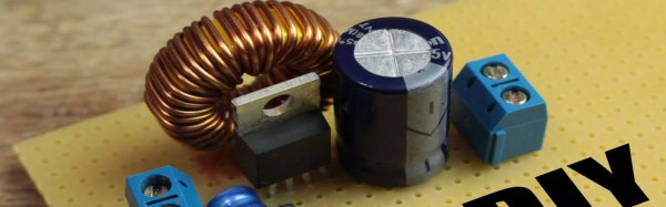
In the last minute of the video he shows how to hook up off-the-shelf switching regulators, whose support components are now completely demystified as the basic principles are understood. Video after the break.

Continue reading “How Does A Buck Converter Work Anyway?”

How To Design Your Own LED Driver

If you find yourself in need of a driver for a high power string of LEDs this is a must read. [Limpkin] just designed this driver as a contract job. He can’t show us the schematic, but he did share some tips on how to build an LED driver around a MAX16834 chip.

As you move to higher power designs the barriers to success pile up rather quickly. Using a chip like the MAX16834 really helps to simplify the task as it can be used as a boost or buck converter, it includes functionality that allows for dimming, and it’s a constant currents solution. There are board design issues that need to be accounted for in these designs. [Limkin] included links to a few calculators that will help you determine trace width based power levels used with the driver. He also recommends using copper pours on both sides of the board connected with vias to help dissipate heat. To that end he used an IR thermometer for feedback during testing.

It’s too bad he doesn’t have any photos of the device at work. If you build something similar please take some pictures and tip us off about it.

Building A Power Supply Around A DC-DC Converter

The EEVblog is on a roll with interesting topics lately. In the latest episode [Dave] takes us through the nitty-gritty of switch mode power supply design. Using DC-DC converter IC’s in not especially hard. The datasheets tend to have fairly good usage schematics but there’s always a bit of heartache that goes into figuring out which external components will make for an optimal design. Get your calculator out and, in the video after the break, he’ll walk you through choosing component values based on the formulas for the MC34063 converter chip.

[Dave] makes the point that this is an extremely common chip, available from several manufacturers, and often found in consumer electronics. In fact, the switchmode supply hack from last month was using a regulator based around the MC34063. So you can buy it or scavenge for it. One thing to note though, we checked Mouser and Digikey and they’re pretty short on these chips right now. Plan your projects accordingly.

Continue reading “Building A Power Supply Around A DC-DC Converter”