555 Timer On Its Own In Electronic Dice

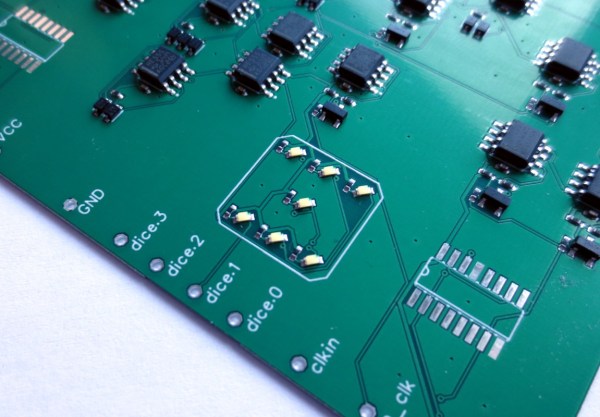
One of the most common clichés around here is that a piece of equipment chosen for a project is always too advanced. If a Raspberry Pi was used, someone will say they should have used an Arduino. If they use an Arduino, it should have been an ATtiny. And of course, if an ATtiny was used, there should have simply been a 555 timer. This time, however, [Tim] decided to actually show how this can be done by removing some of the integrated circuits from an electronic dice and relying entirely on the 555 timer for his build.

The electronic dice that [Tim] has on hand makes use of two main ICs: a NE555 and a CD4017 which is a decade counter/divider used for cycling through states. In order to bring the 555 to the forefront of this build, he scraps the CD4017 and adds an array of 555 timers. These are used to generate the clock signals necessary for this build but can also be arranged to form logic circuits. This comes at a great cost, however. The 555 chips take up an unnecessarily large area on the PCB (even though these are small surface-mount chips), consume an incredible amount of power, and are very slow. That’s fine for an electronic dice-rolling machine like this one, but that’s probably where [Tim] will leave this idea.

The 555 timer is a surprisingly versatile chip, and this project shows that there is some element of truth to the folks claiming that projects need naught but a few 555s. We’ve seen entire CPUs built using nothing but 555s, and even a classic project that uses a 555 timer to balance a robot.

Breathtaking Alarm Clock Looks Like It Came From A 1960 Fallout Shelter

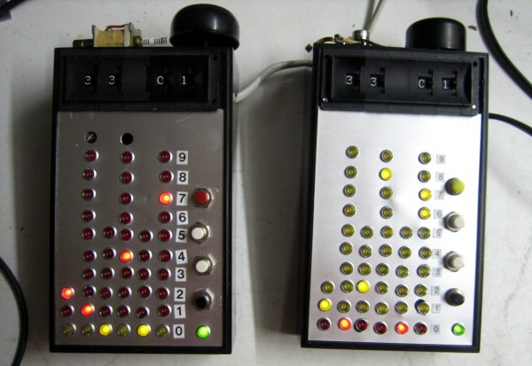
All the hardcore geeks have alarm clocks where the bell striker is a hard disk read head… or at least they’ll be building them after seeing this. [Senile Data Systems] created an industrial voltage alarm clock out of decade counters that looks like it was unearthed from a fallout shelter (machine translation).

At first glace you might mistake this for a binary clock since it uses a column of LEDs to indicate each digit of 24-hour time. It’s not, as each row corresponds to a pin on the CD4017 decade counters that make up the timekeeping circuit inside.

Thumbscrew wheel switches at the top of the bulky handheld unit are how the alarm time is set, triggering a bell along the top edge. The clock is driven by the 50 Hz line voltage and [SDS] tried using that AC to drive a solenoid as the striker on the prototype unit but it performed poorly. The use of a hard disk read head turns out to be the perfect striker, as heard in the video after the break. As for triggering from the decade counters, here’s what [SDS] told us about the design:

The switches’ outputs gets ANDed with a 10 Hz signal (on a 60 Hz grid it will become 12 Hz). This drives a slightly beefy transistor which in turn drives an electromagnet to hammer a bell which broke off my bicycle. Yes. This is a digital analog alarm clock. The clock portion is digital but the bell is analog and sounds like Grampa’s old wind up alarm clock.

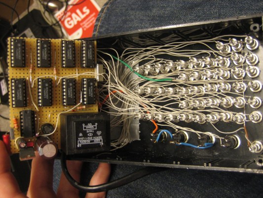
The build came about when a cache of over 600 industrial LEDs (24 V – 48 V) fell into his lap. This makes the insides of the clock something to behold as point-to-point soldering connects the panel mount lights and all nine logic chips. Add in that transformer for getting the line voltage and we imagine this thing has quite a bit of heft to it.

If you’ve ever had an alarm with a wind-up bell you know there’s no better way to jolt yourself out of a peaceful slumber and into the chaos of the real world. If the gentle tinkle of the hard drive head isn’t enough for you, this fire bell alarm clock will certainly do the trick.


Continue reading “Breathtaking Alarm Clock Looks Like It Came From A 1960 Fallout Shelter”

Combo Lock Uses Relays And Logic Gates

logic-combo-lock

Here’s a really fascinating circuit that implements a combination lock using relays and logic gates. Even with the schematic and written explanation of how it works we’re still left somewhat in the dark. We’ll either pull out some paper and do it by hand this weekend, or build it chunk by chunk in a simulator like Atanua. Either way, the project sparked our interest enough that we want to get elbow deep into its inner workings.

From the description we know that it uses a combination of CD4017, CD4030, CD4072, and CD4081 chips. You’re probably familiar with the 4017 which is a decade counter popular in a lot of project. The other chips provide XOR, OR, and AND gates respectively. The relays were chosen for two purposes. One of them activates when a correct combination has been entered, effectively serving as the output for the combo lock. The other two are for activating the clock and affecting a reset if the wrong combination is entered.

It makes us wonder if this would be incredibly simple to brute force the combination by listening for sound of the reset relay activating? It’s hard to tell from the video after the break if you can discern a wrong digit from a right once just based on sound.

Continue reading “Combo Lock Uses Relays And Logic Gates”

Blinky Headgear

This hat has a chasing LED feature thanks to our old friend the 555 timer. [BananaSlug] even built in the option to change the speed at the push of a button.

His design starts out with a costume hat. Each of the 25 LEDs is soldered to a 2×4 hole chunk of protoboard. The LED package is pushed through a slit in the hat, but the protoboard remains on the inside where it can be sewn in place. From there [BananaSlug] soldered one negative bus around the circumference, and an individual positive lead from each module back to the control board. They’re addressed by a set of CD4017 decade counters which are clocked by the 555 timer circuit.

This is a great little analog/logic project and the style is perfect if you’ve got the coat to go along with it.

Challenge: Figure Out How This Logic-based Chaser Works

[Andrea] built this LED chaser using one logic chip. It illuminates all but one of the six LEDs, with the dim bit moving back and forth along the row in a chase sequence. This is something like an inverse Larson Scanner without the fading tail. But doing it with a logic chip instead of a microcontroller is a fun challenge.

Which brings us to the point of this feature. [Andrea] didn’t really post an explanation of how the circuit works. Usually missing details mean that we archive the tip and move on to the next one, but we think this provides a fun activity. Can you figure out how the circuit works? We already know that it’s using a CD4017 decade counter/divider chip. This gets its clock signal from a 555 timer circuit. [Andrea’s] schematic is a bit hard to read, but grab a copy, blow it up a bit (or use your browser zoom) and study the CD4017 datasheet (PDF) if you need to.

Want proof that it does actually work? It’s embedded after the break.

Continue reading “Challenge: Figure Out How This Logic-based Chaser Works”