Fail Of The Week: CPLDs That Release Blue Smoke

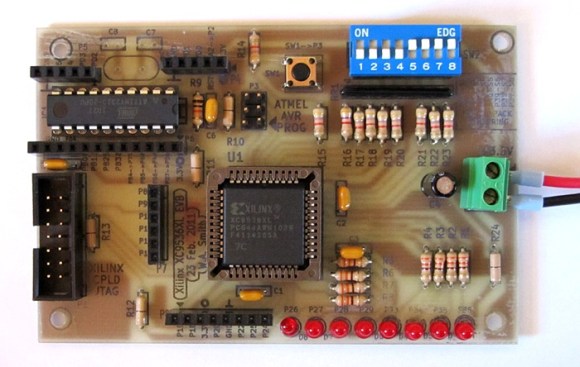
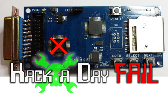
The card you see above is a floppy drive emulator for Macintosh. [Steve Chamberlain] has been hand assembling these and selling them in small runs, but is troubled by about a 4% burn-out rate for the CPLD which has the red ‘X’ on it. He settled into figure out what exactly is leading to this and it’s a real head-scratcher.

He does a very good job of trouble-shooting, starting with a list of all the possible things he thinks could be causing this: defective part, bad PCB, bad uC firmware, damage during assembly, solder short, tolerance issues, over-voltage on the DB connector, or bad VHDL design. He methodically eliminates these, first by swapping out the part and observing the exact same failure (pretty much eliminates assembly, solder short, etc.), then by measuring and scoping around the card.

The fascinating read doesn’t stop with the article. Make sure you work your way through the comments thread. [Steve] thinks he’s eliminated the idea of bad microcontroller code causing damage. He considers putting in-line resistors on the DB connector but we wonder if clamping diodes wouldn’t be a better choice (at least for testing purposes)? This begs the question, why is he observing a higher voltage on those I/O lines during power-up? As always, we want to hear your constructive comments below.


2013-09-05-Hackaday-Fail-tips-tileFail of the Week is a Hackaday column which runs every Wednesday. Help keep the fun rolling by writing about your past failures and sending us a link to the story — or sending in links to fail write ups you find in your Internet travels.

Editing Circuits With Focused Ion Beams

CPLD

[Andrew] has been busy running a class on hardware reverse engineering this semester, and figured a great end for the class would be something extraordinarily challenging and amazingly powerful. To that end, he’s editing CPLDs in circuit, drilling down to metal layers of a CPLD and probing the signals inside. It’s the ground work for reverse engineering just about every piece of silicon ever made, and a great look into what major research labs and three-letter agencies can actually do.

The chip [Andrew] chose was a Xilinx XC2C32A, a cheap but still modern CPLD. The first step to probing the signals was decapsulating the chip from its plastic prison and finding some interesting signals on the die. After working out a reasonable functional diagram for the chip, he decided to burrow into one of the lines on the ZIA, the bus between the macrocells, GPIO pins, and function blocks.

Actually probing one of these signals first involved milling through 900 nm of silicon nitride to get to a metal layer and one of the signal lines. This hole was then filled with platinum and a large 20 μm square was laid down for a probe needle. It took a few tries, but [Andrew] was able to write a simple ‘blink a LED’ code for the chip and view the s square wave from this test point. not much, but that’s the first step to reverse engineering the crypto on a custom ASIC, reading some undocumented configuration bits, and basically doing anything you want with silicon.

This isn’t the sort of thing anyone could ever do in their home lab. It’s much more than just having an electron microscope on hand; [Andrew] easily used a few million dollars worth of tools to probe the insides of this chip. Still, it’s a very cool look into what the big boys can do with the right equipment.


Learn JTAG By Writing A Bit-banging Programmer

j-tag-flow-chart

[Pesco] won one of Dangerous Prototypes’ PCB giveaways a few months ago. He opted for a CPLD breakout board. He just needed to put in a parts order and populate the components himself. But then what? He needed a JTAG programmer to work with the chip. Like any good autodidact he choose to make his own rather than buying one. He absorbed the JTAG specification and coded a bit banging programmer using an Arduino.

We’ve used JTAG many times to program ARM chips. But until now we never took the time to figure out how the specification works. If you’ve got an IEEE subscription you can download the whitepaper, but [Pesco] was also able to find one floating around on the interwebs. The flow chart on the left is the cheat sheet he put together based on his readings. From there he wrote the Arduino sketch which implements the programming standard, allowing him to interact with a chip through a minicom terminal window.

[via Dangerous Prototypes]

Evalbot As A JTAG Programmer

evalbot-as-jtag-programmer

[Adarsh] needed a JTAG programmer to push code to a CPLD dev board he was working with. He knew he didn’t have a dedicated programmer but figured he could come up with something. Pictured above is his hack to use a Stellaris Evalbot as a programmer.

Long time readers will remember the Evalbot coupon code debacle of 2010. The kits were being offered with a $125 discount as part of a conference. We were tipped off about the code not know its restrictions, and the rest is history. We figure there’s a number of readers who have one collecting dust (except for people like [Adam] that used it as a webserver). Here’s your chance to pull it out again and have some fun.

A bit of soldering to test points on the board is all it takes. The connections are made on the J4 footprint which is an unpopulated ICDI header. On the software side [Adarsh] used OpenOCD with stock configuration and board files (specifics in his writeup) to connect to the white CPLD board using JTAG.

Etch Your Own CPLD Development Board

etch-your-own-cpld-breakout

Ever wanted to make the jump from microcontrollers to logic chips? Although not technically the same thing we consider FPGA and CPLD devices to be in similar categories. Like FPGAs, Complex Programmable Logic Devices let you build hardware inside of a chip. And if you’ve got the knack for etching circuit boards you can now build your own CPLD development module. Long-time Hackaday readers will remember our own offering in this area.

Our years of microcontroller experience have taught us a mantra: if it doesn’t work it’s a hardware problem. We have a knack for wasting hours trying to figure out why our code doesn’t work. The majority of the time it’s a hardware issue. And this is why you might not want to design your own dev tools when just starting out. But one thing this guide has going for it is incremental testing. After etching and inspecting the board, it is populated in stages. There is test code available for each stage that will help verify that the hardware is working as expected.

The CPLD is programmed using that 10-pin header. If you don’t have a programmer you can build your own that uses a parallel port. Included on the board is an ATtiny2313 which is a nice touch as it can simulate all kinds of different hardware to test with your VHDL code. There is also a row of LEDs, a set of DIP switches, and a few breakout headers to boot.

CPLD Motor Control

[Chris] continues cranking out the tutorials, this time around he’s showing how to use a CPLD for simple motor control. The demo hardware is pretty basic, he built his own FPGA/CPLD demo board a few years back which used a PLCC socket for easy interfacing. You should be able to use just about any gear you have on hand.

Of course the thing about these chips is that you’re working with hardware that can be run in parallel. [Chris] mentions that this is what makes it perfect for timing-critical applications. Here he’s using a motor driver that monitors a PWM signal, using the duty cycle to actuate the direction and speed at which the motor turns. After the break you can see a demonstration of the CPLD reading from an ADC chip and converting the value to a PWM signal. [Chris] has also used the same hardware for VGA signals; something that is usually a timing nightmare if done with a microcontroller.

If this leaves you thirsting for more CPLD goodness check out our own guide on the subject.

Continue reading “CPLD Motor Control”

Want 2 Megabytes Of SRAM For Your Arduino?

How much memory do you really need? We suppose it’s not really our place to judge how you misuse use memory in your projects. But we do appreciate the clean and orderly technique that [Eric Rogers] uses to add multiple SPI SRAM chips to an Arduino.

The heavy lifting is done with a CPLD shield called the Amani 64. It intercepts the SPI calls from the Arduino to an SRAM chip, and translates the address information to find the appropriate data on a collection of 23K256 devices. These chips are inexpensive, and using several of them provides a savings over choosing a single SPI addressable chip with a larger memory size.

The best part is that the flexibility of the CPLD allowed [Eric] to devise an addressing system that takes advantage of unused bits in the Arduino’s SPI data transfer functions. When using a single 23K256 chip, there are four write functions that waste a total of six bits. He devised a method to inject addressing data into these unused bits, allowing him to address up to 64 different memory chips for a potential of 2 MB of storage. The CPLD pulls out this injected address and subsequently writes or reads the bank of SRAM chips.

Looking for other SRAM upgrade options? Here’s another one that uses multiplexing to decrease the address lines necessary to add memory.