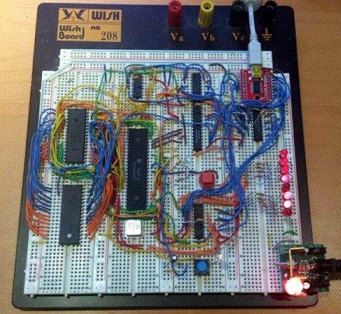
THP Entry: A CPLD Video Card With VGA And NTSC

NTSC

[PK] is working on a very simple video card, meant to output 640×480 VGA with a cheap CPLD. The interface will be 5 Volt SPI, meaning there’s a ton of potential here for anyone wanting put a reasonable (and cheap) display in a microcontroller project. The project has come a long way, and his latest update showcases something that has only been done once before: color NTSC with programmable logic

The brains of the outfit is a $5, 100-pin CPLD from Xilinx. Apart from that, the rest of the components are a crystal, PLL, and an almost hilarious number of resistors for the R2R ladder. The one especially unique component is the 25.056815 MHz crystal – multiply by that by two, and it’s fast enough to drive a VGA monitor. Divide the crystal by seven, it’s the 3.579545 MHz you need for an NTSC colorburst frequency. That’s VGA and NTSC in a single programmable logic project, something the one FPGA project we could find that did color NTSC couldn’t manage.

The next step in the project is designing a PCB and figuring out the code for the framebuffer. [PK] put up a demo showing off both VGA and NTSC; you can check that out below.


SpaceWrencherThe project featured in this post is an entry in The Hackaday Prize. Build something awesome and win a trip to space or hundreds of other prizes.

Continue reading “THP Entry: A CPLD Video Card With VGA And NTSC”

An Online Course For FPGA And CPLD Development

FPGA

Over on the University of Reddit there’s a course for learning all about FPGAs and CPLDs. It’s just an introduction to digital logic, but with a teacher capable of building a CPLD motor control board and a video card out of logic chips, you’re bound to learn something.

The development board being used for this online course is an Altera EMP3032 CPLD conveniently included in the Introduction to FPGA and CPLD kit used in this course. It’s not a powerful device by any measure; it only has 32 macrocells and about 600 usable gates. You won’t be designing CPUs with this thing, but you will be able to grasp the concept of designing logic with code.

Future lessons include building binary counters, PWM-controlled LEDs, and a handheld LED POV device. In any event, it’s a great way to learn about how programmable logic actually works, and a fairly cheap way to get into the world of FPGAs and CPLDs. Introductory video below.

Continue reading “An Online Course For FPGA And CPLD Development”

Programmable Logic II – CPL

There is a wide assortment of cheap development (dev) boards for Complex Programmable Logic Devices (CPLD), the smaller cousin of the Field Programmable Logic Array (FPLA)

Using an inexpensive board and the development software that’s free to download from the major programmable companies such as Xilinx and Altera, the only additional thing needed is a programmer module. Cheap ones are available on Ebay but I am hoping that someone takes the time to teach an ARM/Arduino to step in as a programmer.

I have a small collection of dev boards including some Ebay specials and also designs I did a few years ago to choose from. For today I am grabbing a newer board that has not been fully checked out yet; an Altera Max V device. I have stuffed the CPLD, the clock oscillator, some LED’s and part of the onboard power supply along with the JTAG header needed to program the CPLD and that’s about it.


Herdware CPLD 5M570ZT
Herdware CPLD 5M570ZT dedicated PCB with SRAM.


CPLD Schematic
CPLD Schematic showing an Altera CPLD 5M570T144

Continue reading “Programmable Logic II – CPL”

CPLD Tutorial: Learn Programmable Logic The Easy Way

The guys over at hackshed have been busy. [Carl] is making programmable logic design easy with an 8 part CPLD tutorial. (March 2018: Link dead.  Try the Wayback Machine.) Programmable logic devices are one of the most versatile hardware building blocks available to hackers. They also can have a steep learning curve. Cheap Field Programmable Gate Arrays (FPGA) are plentiful, but can have intricate power requirements. Most modern programmable logic designs are created in a Hardware Description Language (HDL) such as VHDL or Verilog. Now you’ve got a new type of device, a new language, an entirely new programming paradigm, and a complex IDE to learn all at once. It’s no wonder FPGAs have sent more than one beginner running for the hills.

The tutorial cuts the learning curve down in several ways. [Carl] is using Complex Programmable Logic Devices (CPLD). At the 40,000 foot level, CPLDs and FPGAs do the same thing – they act as re-configurable logic. FPGAs generally do not store their configuration – it has to be loaded from an external FLASH, EEPROM, or connected processor. CPLDs do store their configuration, so they’re ready as soon as they power up. As a general rule, FPGAs contain more configurable logic than CPLDs. This allows for larger designs to be instantiated with FPGAs. Don’t knock CPLDs though. CPLDs have plenty of room for big designs, like generating VGA signals.

[Carl] also is designing with schematic capture in his tutorial. With the schematic capture method, digital logic schematics are drawn just as they would be in Eagle or KiCad. This is generally considered an “old school” method of design capture. A few lines of VHDL or Verilog code can replace some rather complex schematics. [Carl’s] simple designs don’t need that sort of power though. Going the schematic capture route eliminates the need to learn VHDL or Verilog.

[Carl’s] tutorial starts with installing Altera’s Quartus II software. He then takes the student through the “hardware hello world” – blinking an LED.  By the time the tutorial is done, the user will learn how to create a 4 bit adder and a 4 bit subtractor. With all that under your belt, you’re ready to jump into big designs – like building a retrocomputer.

[Image via Wikimedia Commons]

Fail Of The Week: CPLDs That Release Blue Smoke

The card you see above is a floppy drive emulator for Macintosh. [Steve Chamberlain] has been hand assembling these and selling them in small runs, but is troubled by about a 4% burn-out rate for the CPLD which has the red ‘X’ on it. He settled into figure out what exactly is leading to this and it’s a real head-scratcher.

He does a very good job of trouble-shooting, starting with a list of all the possible things he thinks could be causing this: defective part, bad PCB, bad uC firmware, damage during assembly, solder short, tolerance issues, over-voltage on the DB connector, or bad VHDL design. He methodically eliminates these, first by swapping out the part and observing the exact same failure (pretty much eliminates assembly, solder short, etc.), then by measuring and scoping around the card.

The fascinating read doesn’t stop with the article. Make sure you work your way through the comments thread. [Steve] thinks he’s eliminated the idea of bad microcontroller code causing damage. He considers putting in-line resistors on the DB connector but we wonder if clamping diodes wouldn’t be a better choice (at least for testing purposes)? This begs the question, why is he observing a higher voltage on those I/O lines during power-up? As always, we want to hear your constructive comments below.


2013-09-05-Hackaday-Fail-tips-tileFail of the Week is a Hackaday column which runs every Wednesday. Help keep the fun rolling by writing about your past failures and sending us a link to the story — or sending in links to fail write ups you find in your Internet travels.

Editing Circuits With Focused Ion Beams

CPLD

[Andrew] has been busy running a class on hardware reverse engineering this semester, and figured a great end for the class would be something extraordinarily challenging and amazingly powerful. To that end, he’s editing CPLDs in circuit, drilling down to metal layers of a CPLD and probing the signals inside. It’s the ground work for reverse engineering just about every piece of silicon ever made, and a great look into what major research labs and three-letter agencies can actually do.

The chip [Andrew] chose was a Xilinx XC2C32A, a cheap but still modern CPLD. The first step to probing the signals was decapsulating the chip from its plastic prison and finding some interesting signals on the die. After working out a reasonable functional diagram for the chip, he decided to burrow into one of the lines on the ZIA, the bus between the macrocells, GPIO pins, and function blocks.

Actually probing one of these signals first involved milling through 900 nm of silicon nitride to get to a metal layer and one of the signal lines. This hole was then filled with platinum and a large 20 μm square was laid down for a probe needle. It took a few tries, but [Andrew] was able to write a simple ‘blink a LED’ code for the chip and view the s square wave from this test point. not much, but that’s the first step to reverse engineering the crypto on a custom ASIC, reading some undocumented configuration bits, and basically doing anything you want with silicon.

This isn’t the sort of thing anyone could ever do in their home lab. It’s much more than just having an electron microscope on hand; [Andrew] easily used a few million dollars worth of tools to probe the insides of this chip. Still, it’s a very cool look into what the big boys can do with the right equipment.


Learn JTAG By Writing A Bit-banging Programmer

j-tag-flow-chart

[Pesco] won one of Dangerous Prototypes’ PCB giveaways a few months ago. He opted for a CPLD breakout board. He just needed to put in a parts order and populate the components himself. But then what? He needed a JTAG programmer to work with the chip. Like any good autodidact he choose to make his own rather than buying one. He absorbed the JTAG specification and coded a bit banging programmer using an Arduino.

We’ve used JTAG many times to program ARM chips. But until now we never took the time to figure out how the specification works. If you’ve got an IEEE subscription you can download the whitepaper, but [Pesco] was also able to find one floating around on the interwebs. The flow chart on the left is the cheat sheet he put together based on his readings. From there he wrote the Arduino sketch which implements the programming standard, allowing him to interact with a chip through a minicom terminal window.

[via Dangerous Prototypes]