All-Band Receiver Lets You Listen To All The Radio At Once

There are many ways to build a radio receiver, but most have a few things in common, such as oscillators, tuned circuits, detectors, mixers, and amplifiers. Put those together in the right order and you’ve got a receiver ready to tune in whatever you want to listen to. But if you don’t really care about tuning and want to hear everything all at once, that greatly simplifies the job and leaves you with something like this homebrew all-band receiver.

Granted, dispensing with everything but a detector and an audio amplifier will seriously limit any receiver’s capabilities. But that wasn’t really a design concern for [Ido Roseman], who was in search of a simple and unobtrusive way to monitor air traffic control conversations while flying. True, there are commercially available radios that tune the aviation bands, and there are plenty of software-defined radio (SDR) options, but air travel authorities and fellow travelers alike may take a dim view of an antenna sticking out of a pocket.

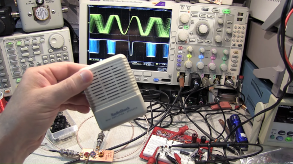
So [Ido] did a little digging and found a dead-simple circuit that can receive signals from the medium-wave bands up into the VHF range without regard for modulation. The basic circuit is a Schottky diode detector between an antenna and a high-gain audio amplifier driving high-impedance headphones; [Ido] built a variation that also has an LM386 amplifier stage to allow the use of regular earbuds, which along with a simple 3D-printed case aids in the receiver’s stealth.

With only a short piece of wire as an antenna, reception is limited to nearby powerful transmitters, but that makes it suitable for getting at least the pilot side of ATC conversations. It works surprisingly well — [Ido] included a few clips that are perfectly understandable, even if the receiver also captured things like cell phones chirping and what sounds like random sferics. It seems like a fun circuit to play with, although with our luck we’d probably not try to take it on a plane.

Fail Of The Week: The SMD Crystal Radio That Wasn’t

The crystal radio is a time-honored build that sadly doesn’t get much traction anymore. Once a rite of passage for electronics hobbyists, the classic coil-on-an-oatmeal-carton and cat’s whisker design just isn’t that easy to pull off anymore, mainly because the BOM isn’t really something that you can just whistle up from DigiKey or Mouser.

Or is it? To push the crystal radio into the future a bit, [tsbrownie] tried to design a receiver around standard surface-mount inductors, and spoiler alert — it didn’t go so well. His starting point was a design using a hand-wound air-core coil, a germanium diode for a detector, and a variable capacitor that was probably scrapped from an old radio. The coil had three sections, so [tsbrownie] first estimated the inductance of each section and sourced some surface-mount inductors that were as close as possible to their values. This required putting standard value inductors in series and soldering taps into the correct places, but at best the SMD coil was only an approximation of the original air-core coil. Plugging the replacement coil into the crystal radio circuit was unsatisfying, to say the least. Only one AM station was heard, and then only barely. A few tweaks to the SMD coil improved the sensitivity of the receiver a bit, but still only brought in one very local station.

[tsbrownie] chalked up the failure to the lower efficiency of SMD inductors, but we’re not so sure about that. If memory serves, the windings in an SMD inductor are usually wrapped around a core that sits perpendicular to the PCB. If that’s true, then perhaps stacking the inductors rather than connecting them end-to-end would have worked better. We’d try that now if only we had one of those nice old variable caps. Still, hats off to [tsbrownie] for at least giving it a go.

Note: Right after we wrote this, a follow-up video popped up in our feed where [tsbrownie] tried exactly the modification we suggested, and it certainly improves performance, but in a weird way. The video is included below if you want to see the details.

Continue reading “Fail Of The Week: The SMD Crystal Radio That Wasn’t”

RFID From First Principles And Saving A Cat

[Dale Cook] has cats, and as he readily admits, cats are jerks. We’d use stronger language than that, but either way it became a significant impediment to making progress with an RFID-based sensor to allow his cats access to their litterbox. Luckily, though, he was able to salvage the project enough to give a great talk on RFID from first principles and learn about a potentially tragic mistake.

If you don’t have 20 minutes to spare for the video below, the quick summary is that [Dale]’s cats are each chipped with an RFID tag using the FDX-B protocol. He figured he’d be able to build a scanner to open the door to their playpen litterbox, but alas, the read range on the chip and the aforementioned attitude problems foiled that plan. He kept plugging away, though, to better understand RFID and the electronics that make it work.

To that end, [Dale] rolled his own RFID reader pretty much from scratch. He used an Arduino to generate the 134.2-kHz clock signal for the FDX-B chips and to parse the returned data. In between, he built a push-pull driver for the antenna coil and an envelope detector to pull the modulated data off the carrier. He also added a low-pass filter and a comparator to clean up the signal into a nice square wave, which was fed into the Arduino to parse the Differential Manchester-encoded data.

Although he was able to read his cats’ chips with this setup, [Dale] admits it was a long road compared to just buying a Flipper Zero or visiting the vet. But it provided him a look under the covers of RFID, which is worth a lot all by itself. But more importantly, he also discovered that one cat had a chip that returned a code different than what was recorded in the national database. That could have resulted in heartache, and avoiding that is certainly worth the effort too.

Continue reading “RFID From First Principles And Saving A Cat”

JFET Stands In For Triode In This Infinite Impedance Detector

An “Infinite Impedance Detector” might sound a little like something that [Zaphod Beeblebrox] would use to zip around the galaxy. It’s not, of course, but it is an interesting and useful demodulator for AM radio signals, as [Sebastian Westerhold] over at Baltic Labs explains in the brief but well-done video below.

If you’ve ever browsed through schematics of old vacuum tube radios, [Sebastian]’s JFET-based detector circuit might look strangely familiar. That’s because this demodulator is about as close to a direct translation between a vacuum tube circuit and a silicon circuit as possible. In fact, [Sebastian] even used literature from the triode version of this detector to figure out the values for some of the components. The only active component is a BF256B JFET; the rest are a small handful of resistors and caps. Construction is in the ever-popular ugly style.

The test setup is simple — a function generator set to 455 kHz and modulated with a 1,000 Hz sine wave. The detector demodulates the audio signal very cleanly, judging by the oscilloscope traces. Just for fun, [Sebastian] also tried a 10.7 MHz carrier with a 1,500 Hz audio modulation, and that worked fine too. He also tried a variation on the circuit with an IF transformer on the input. That circuit works just about the same as the transformerless version, although it does provide a little gain.

Earth-shattering stuff? Probably not. But it does show the fun you can have with a scrap of PCB and a few components, and seems like it could easily be the kind of project that would take you down the RF rabbit hole. Thanks to [Sebastian] for sharing this one with us.

Continue reading “JFET Stands In For Triode In This Infinite Impedance Detector”

Multiband Crystal Radio Set Pulls Out All The Stops

Most crystal radio receivers have a decidedly “field expedient” look to them. Fashioned as they often are from a few turns of wire around an oatmeal container and a safety pin scratching the surface of a razor blade, the whole assembly often does a great impersonation of a pile of trash whose appearance gives little hope of actually working. And yet work they do, usually, pulling radio signals out of thin air as if by magic.

Not all crystal sets take this slapdash approach, of course, and some, like this homebrew multiband crystal receiver, aim for a feature set and fit and finish that goes way beyond the norm. The “Husky” crystal set, as it’s called by its creator [alvenh], looks like it fell through a time warp right from the 1920s. The electronics are based on the Australian “Mystery Set” circuit, with modifications to make the receiver tunable over multiple bands. Rather than the traditional galena crystal and cat’s whisker detector, a pair of1N34A germanium diodes are used as rectifiers — one for demodulating the audio signal, and the other to drive a microammeter to indicate signal strength. A cat’s whisker is included for looks, though, mounted to the black acrylic front panel along with nice chunky knobs and homebrew rotary switches for band selection and antenna.

As nice as the details on the electronics are, it’s the case that really sells this build. Using quarter-sawn oak salvaged from old floorboards. The joinery is beautiful and the hardware is period correct; we especially appreciate the work that went into transforming a common flat washer into a nickel-plated escutcheon for the lock — because every radio needs a lock.

Congratulations to [Alvenh] for pulling off such a wonderful build, and really celebrating the craftsmanship of the early days of radio. Need some crystal radio theory before tackling your build? Check out [Greg Charvat]’s crystal radio deep dive.

Educational Radio, Educates

Analyzing and troubleshooting a modern AM/FM radio, digital radio, or TV can be a pretty daunting task. However, a common AM radio is easy to understand, experiment with, and repair. Learning about that will help you understand more complex circuits later. That’s the idea behind the Elenco AM radio which is built on a wide-open PCB with markings for all the important sections. [The Offset Volt] uses one of these to explain how a receiver works, especially how a diode detects the signal and how the automatic gain control works.

Between a series of diagrams and live scope demonstrations, you can see the effects of capacitance in the receiver along with other circuit effects.

Continue reading “Educational Radio, Educates”

FM Signal Detection The Pulse-Counting Way

Compared to the simple diode needed to demodulate AM radio signals, the detector circuits used for FM are slightly more complicated. Wrapping your head around phase detectors, ratio detectors, discriminators, and quadrature detectors can be quite an exercise. There’s another demodulation method that’s not so common, but thankfully it’s also pretty easy to understand: the pulse counting detector.

As [Allan (W2AEW)] notes in the video below, pulse counting is a bit of a misnomer. Pulse counting works by generating a narrow, fixed-width square wave pulse at a set point in the received FM signal’s waveform, usually at the zero-crossing point. Since the frequency of the modulated carrier changes, the duty cycle of the resulting pulse train varies. That means there will be a fixed number of pulses, but by taking the average voltage of the pulse train, we can tease out the original audio frequency signal.

Simple in theory is often more complicated in practice, and [W2AEW] goes into some detail about those complications, such as needing to use a down-converter to make the peak-to-peak frequency deviation in the pulse train more easily detectable. As is his style, he walks us through a test circuit to prove that the theory works in practice. A simple two-transistor circuit generates the pulses at the zero-crossing point, a low-pass filter cleans up the signal, and a cheap audio amplifier reproduces the original audio. It’s a crude circuit to be sure, relying on the stray capacitance of the breadboard to work, but it proves the point and serves as a jumping-off point for further experiments – perhaps using an Arduino to count the pulses?

We always enjoy [W2AEW]’s videos and learn a lot from them. Not long ago we featured another of his videos talking about the mysteries of RF modulation; SSB, anyone?

Continue reading “FM Signal Detection The Pulse-Counting Way”