A while back, [heypete] needed to get a GPS timing receiver talking to a Raspberry Pi. The receiver only spoke RS-232, and the Pi is TTL level serial. [Pete] picked up a few RS-232 to TTL conversion boards from an online vendor in China. These boards were supposedly based on the Max3232, a wonderchip that converts the TTL serial to the positive and negative voltages of RS-232 serial. The converters worked fine for a few weeks, before failing, passing a bunch of current, and overheating.
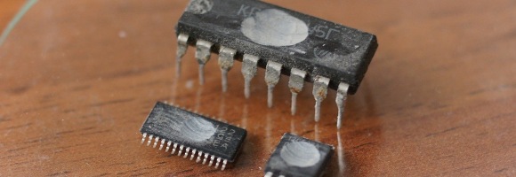
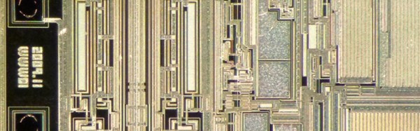
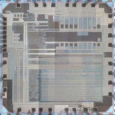
On Mouser and Digikey, the Max3232 costs about $1.80 in quantity one, and shipping is extra. You can pick up a ‘Max3232 converter board’ from the usual online marketplaces for seventy five cents with free shipping. Of course the Chinese version is fake. [Pete] had some nitric acid, and decided to compare the die of the real and fake Max3232s.
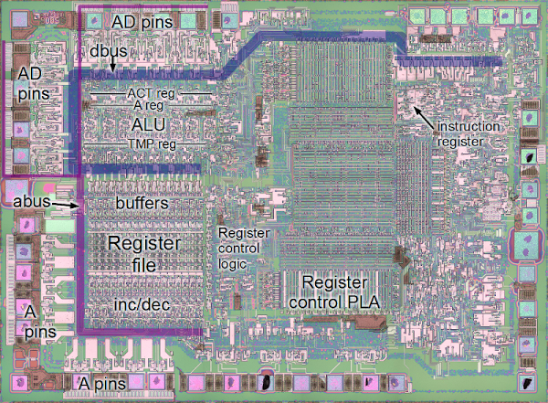
After desoldering two fake chips from their respective converter boards, and acquiring a legitimate chip straight from Maxim, [Pete] took a look at the chips under the microscope. The laser markings on the fakes are inconsistent, but there was something interesting to be found in the date code markings. It took two to four weeks for the fake chips to be etched with a date code, assembled into a converter board, shipped across the planet, put into [Pete]’s project, run for a little bit, and fail spectacularly. That’s an astonishing display of manufacturing, logistics, and shipping times. Update: The date codes on the fakes had 2013 laser etched on the plastic package, and 2009 on the die. The real chips had a date code just a few weeks before [Pete] decapped them — a remarkably short life but they gave in to a good cause.
Following the Zeptobars and CCC (PDF) guides to dropping acid, [Pete] turned his problem into solution and took a look at the dies under a microscope. The legitimate die was significantly larger, and the fake dies were identical. The official die used gold bond wires, but the fake ones didn’t.
Unfortunately, [Pete] isn’t an expert in VLSI, chip design, failure analysis, or making semiconductors out of sand. Anything that should be obvious to the layman is not, and [Pete] has no idea why these chips would work for a week, then overheat and fail. If anyone has an idea, hit [Pete] up and drop a note in the comments.
 Dirty Decapsulation is Dangerous Prototype’s addition to their array of hacker services including