Fail Of The Week: Arachno∙fail∙ia

Going down the list (FCC, CE, UL, etc.) we can’t think of a regulating body that will test for this failure mode. Reportedly, a $1M irrigation system was taken down by a spider. And an itsy-bitsy spider at that.

This fail turned up as a quick image post over on /r/mildlyinteresting but I wasn’t the only electronics person attracted like a moth to a flame. Our friend [Sprite_TM] popped in to answer a question about conformal coating. Seems this board was sealed in a waterproof enclosure but was obviously not conformally coated.

fotw-spider-short-relay-diagram[Sprite_TM] also helped out with some armchair-engineering to guess at what happened. It’s not hard to tell that the footprint on the board looks like a set of mechanical relays all in a line. He looked up the most likely pinout for the relay.

We’ve superimposed that pinout on the board to help illustrate the failure. High voltage comes in on the pin shown with the red trace leading away from it. On either side of that pin are the connections for the low voltage coil which switches from normally closed (the pin in the upper right that is not connected to anything) to the normally open pin (which has the wide trace leading away from it).

So there sat the high voltage pin in between the coil pins when, along came a spider. It shorted the pins and presumably all the way back to the power supply for the low voltage rail. [Fugly_Turnip] (the OP) share some additional detail about the system and this failure; in addition to this card it fried the control module as well.

Another comment on the same thread shares a different story of two boards mounted next to each other with a bug shorting a 1/4″ air gap between two boards and causing similar carnage. Have you encountered Arachno-fail-ia of your own? Let us know below.


2013-09-05-Hackaday-Fail-tips-tileFail of the Week is a Hackaday column which celebrates failure as a learning tool. Help keep the fun rolling by writing about your own failures and sending us a link to the story — or sending in links to fail write ups you find in your Internet travels.

Fail Of The Week: Where’s Me Jumper?

Just in case you imagine that those of us who write for Hackaday are among the elite of engineering talent who never put a foot wrong and whose benches see a succession of perfectly executed builds and amazing hacks, let me disabuse you of that notion with an ignominious failure of my own.

I was building an electronic kit, a few weeks ago. It’s a modular design with multiple cards on a backplane, though since in due course you’ll see a review of it here I’ll save you its details until that moment. In my several decades of electronic endeavours I have built many kits, so this one as a through-hole design on the standard 0.1″ pitch should have presented me with no issues at all. Sadly though it didn’t work out that way.

Things started to go wrong towards the end of the build, I noticed that the temperature regulator on my soldering iron had failed at some point during its construction. Most of it had thus been soldered at a worryingly high temperature, so I was faced with a lot of solder joints to go over and rework in case any of them had been rendered dry by the excessive heat.

In due course when I powered my completed kit up, nothing worked. It must have been the extra heat, I thought, so out came the desolder braid and yet again I reworked the whole kit. Still no joy. Firing up my oscilloscope I could see things happening on its clock and data lines so there was hope, but this wasn’t a kit that was responding to therapy. A long conversation with the (very patient) kit manufacturer left me having followed up a selection of avenues, all to no avail. By this time a couple of weeks of on-and-off diagnostics had come and gone, and I was getting desperate. Somehow I’d cooked this thing with my faulty iron, and there was no way to find the culprit.

Continue reading “Fail Of The Week: Where’s Me Jumper?”

Fail Of The Week: ESP8266 Heats Temperature Sensor

[Richard Hawthorn] sent us in this interesting fail, complete with an attempted (and yet failed) clever solution. We love learning through other people’s mistakes, so we’re passing it on to you.

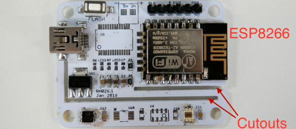
First the obvious-in-retrospect fail. [Richard] built a board with a temperature sensor and an ESP8266 module to report the temperature to the Interwebs. If you’ve ever put your finger on an ESP8266 module when it’s really working, you’ll know what went wrong here: the ESP8266 heated up the board and gave a high reading on the temperature sensor.

temp2Next came the clever bit. [Richard] put cutouts into the board to hopefully stop the flow of heat from the ESP8266 module to the temperature sensor. Again, he found that the board heats up by around four degrees Celcius or nine degrees Farenheit. That’s a horrible result in any units.

What to do? [Richard’s] first ideas are to keep hammering on the thermal isolation, by maybe redoing the board again or adding a heatsink. Maybe a daughterboard for the thermal sensor? We can’t see the board design in enough detail, but we suspect that a flood ground plane may be partly to blame. Try running thin traces only to the temperature section?

[Richard]’s third suggestion is to put the ESP into sleep mode between updates to reduce waste heat and power consumption. He should be doing this anyway, in our opinion, and if it prevents scrapping the boards, so much the better. “Fix it in software!” is the hardware guy’s motto.

But we’ll put the question to you electronics-design backseat drivers loyal Hackaday readers. Have you ever noticed this effect with board-mounted temperature sensors? How did you / would you get around it?


2013-09-05-Hackaday-Fail-tips-tileFail of the Week is a Hackaday column which celebrates failure as a learning tool. Help keep the fun rolling by writing about your own failures and sending us a link to the story — or sending in links to fail write ups you find in your Internet travels.

Fail Of The Week: Don’t Tie Those Serial Lines High

Fail Of The Week is a long-running series here at Hackaday. Over the years we’ve been treated to a succession of entertaining, edifying, and sometimes downright sad cock-ups from many corners of the technological and maker world.

You might think that we Hackaday writers merely document the Fails of others, laughing at others’ misfortunes like that annoying kid at school. But no, we’re just as prone to failure as anyone else, and it is only fair that we eat our own dog food and tell the world about our ignominious disasters when they happen.

And so we come to my week. I had a test process to automate for my contract customer. A few outputs to drive some relays, a few inputs from buttons and microswitches. Reach for an Arduino Uno and a prototyping shield, divide the 14 digital I/O lines on the right into 7 outputs and 7 inputs. Route 7 to 13 into a ULN2003 to drive my relays, tie 0 to 6 high with a SIL resistor pack so I can trigger them with switches to ground. Job done, and indeed this is substantially the hardware the test rig ended up using.

So off to the Arduino IDE to write my sketch. No rocket science involved, a fairly simple set of inputs, outputs, and timers. Upload it to the Arduino, and the LED on pin 13 flashes as expected. Go for a well-deserved lunch as a successful and competent engineer who can whip up a test rig in no time.

Back at the bench refreshed by the finest British pub grub, I started up the PC, plugged the shield into the Arduino, and applied the power. My sketch worked. But wait! There’s a slight bug! Back to the IDE, change a line or two and upload the sketch.

And here comes my fail. The sketch wouldn’t upload, the IDE reported a COM port error. “Damn’ Windows 10 handling of USB serial ports”, I thought, as I’m not a habitual Windows user on my own machines. Then followed something I’ve not done for quite a while; diving into the Windows control panel to chase the problem. Because it had to be a Windows problem, right?

arduino-serial-pinsThe seasoned Arduinisti among you probably spotted my fail four paragraphs ago. We all know that pins 0 and 1 on an Arduino are shared with the serial port, but who gives it a second thought? I guess I’d always had the good fortune to drive those pins from lines which didn’t enforce a logic state, and had never ended up tying them high. Hold them to a logic 1, and the Arduino can’t do its serial thing so sketches stay firmly in the IDE.

I could have popped the shield off every time I wanted to upload a new sketch, but since in the event I didn’t need all those inputs I just lifted the links tying those pins high and shifted the other inputs up the line. And went home that evening a slightly less competent engineer whose ability to whip up a test rig in no time was a bit tarnished. Ho hum, at least the revised sketch worked and the test rig did its job exactly as it should.

So that’s my Fail Of The Week. What’s yours?

Header image: pighixxx.com, CC-BY-ND via MarkusJenkins


2013-09-05-Hackaday-Fail-tips-tileFail of the Week is a Hackaday column which celebrates failure as a learning tool. Help keep the fun rolling by writing about your own failures and sending us a link to the story — or sending in links to fail write ups you find in your Internet travels.

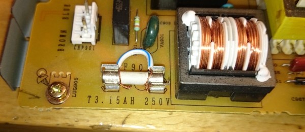
Fail Of The Week: Always Check The Fuse

[Tomas] at Umeå Hackerspace in Sweden had some broken audio equipment, including a Sharp CD player/amplifier. What went wrong when he tried to fix it is a fail story from which we can all learn.

The device worked – for about a second after being turned on, before turning itself off. That’s a hopeful sign, time to start debugging. He took the small-signal and logic boards out of the circuit, leaving only power supply and amplifier, and applied the juice.

Magic blue smoke ensued, coming from the amplifier. Lacking a suitable replacement part, that was it for the Sharp.

On closer inspection it emerged that the previous owner had bypassed the power supply fuse with a piece of copper wire, Evidently they had found the fuse to be blowing too often and instead of trying to fix the problem simply shot the messenger.

We have all probably done it at some time or other. In the absence of a replacement fuse we may have guestimated the number of single strands required to take the current, or used a thin strip of foil wrapped around the fuse body. And we’ll all have laughed at that meme about using a spanner or a live round as a fuse.

So if there’s a moral to this story, it’s to always assume that everyone else is as capable as you are of doing such a dodgy fix, and to always check the fuse.


2013-09-05-Hackaday-Fail-tips-tileFail of the Week is a Hackaday column which celebrates failure as a learning tool. Help keep the fun rolling by writing about your own failures and sending us a link to the story — or sending in links to fail write ups you find in your Internet travels.
Fail Of The Week: Battery Pack Jack Wired Backwards

Last Saturday I had a team of teenage hackers over to build Arduino line-following robots from a kit. Everything went well with the mechanical assembly and putting all the wires on the correct pins. The first test was to check that the motors were moving in the proper direction. I’d written an Arduino program to test this. The first boy’s robot worked fine except for swapping one set of motor leads. That was anticipated because you cannot be totally sure ahead of time which way the motors are going to run.

The motor’s on the second robot didn’t turn at all. As I checked the wiring I smelled the dreaded hot electronics smell but I didn’t see any smoke. I quickly pulled the battery jack from the Arduino and – WOW! – the wires were hot. That didn’t bode well. I checked and the batteries were in the right way. A comparison with another pack showed the wires going into the pack were positioned properly. I plugged in another pack but the motors still didn’t run.

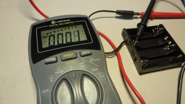
I got my multimeter, checked the voltage on the jack, and it was -5.97 V from center connector to the barrel. The other pack read 6.2 V. I had a spare board and pack so swapped those and the robot worked fine. Clearly the reverse polarity had zapped the motor control ICs. After that everyone had a good time running the robots on a course I’d laid out and went home pleased with their robots.

After they left I used the ohmmeter to check the battery pack and found the wiring was backwards, as you can see in the feature photo. A close inspection showed the wire with a white line, typically indicating positive, indeed went to the positive battery terminal. I shaved the barrel connector down to the wires and the white line wire was connected to the outside of the barrel. FAIL!

This is a particularly bad fail on the part of the battery pack supplier because how hard is it to mess up two wires? You can’t really fault the robot kit vendor because who would expect a battery pack to be bad? The vendor is sending me a new battery pack and board so I’m satisfied. Why did I have an extra board and pack, actually an entire kit? For this exact reason; something was bound to go wrong. Although what I had imagined was for one of the students to break a mechanical part or change wiring and zap something. Instead, we were faced with a self-destructing kit. Prudence paid off.

Fail Of The Week : Watt A Loss

This one is a bit dated, but the lessons are still relevant. [Zach Hoeken] posted about the challenges he faced building a CNC stepper driver. He was experimenting with Toshiba motor drivers back in 2012.

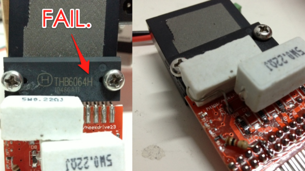
The modular motor driver boards he built were based on the THB6064AH – capable of 1/64th step, and 4.5 Amps at up to 50V. [Zach] built a test jig to run the boards through their paces. A couple of messed tracks was the least of his problems – easily fixed by cutting traces and using jumper wires to correct the errors. But the header footprints for the motor drive boards got reversed. The only way out was to solder the headers on the back side.

LESSON : Always check footprint orientation and pin numbering before sending boards to fab.

The surprising part was when someone as experienced as [Zach] messed up on Ohms Law. Based on the current he wanted the motors to run at, his sense resistors needed to be 3.2W, but he’d used SMD footprints (0805 likely) instead. Those tiny resistors couldn’t be used at all, and the 5W resistors plonked on looked like an ugly hack.

Continue reading “Fail Of The Week : Watt A Loss”