
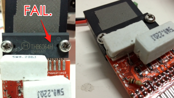
This one is a bit dated, but the lessons are still relevant. [Zach Hoeken] posted about the challenges he faced building a CNC stepper driver. He was experimenting with Toshiba motor drivers back in 2012.
The modular motor driver boards he built were based on the THB6064AH – capable of 1/64th step, and 4.5 Amps at up to 50V. [Zach] built a test jig to run the boards through their paces. A couple of messed tracks was the least of his problems – easily fixed by cutting traces and using jumper wires to correct the errors. But the header footprints for the motor drive boards got reversed. The only way out was to solder the headers on the back side.
LESSON : Always check footprint orientation and pin numbering before sending boards to fab.
The surprising part was when someone as experienced as [Zach] messed up on Ohms Law. Based on the current he wanted the motors to run at, his sense resistors needed to be 3.2W, but he’d used SMD footprints (0805 likely) instead. Those tiny resistors couldn’t be used at all, and the 5W resistors plonked on looked like an ugly hack.

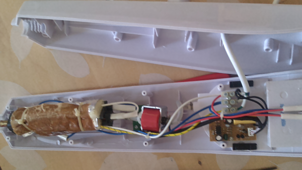

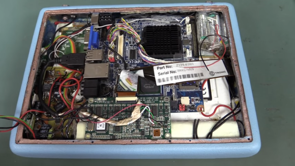
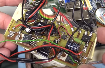 The tablet is based upon an off-the-shelf embedded PC motherboard and touchscreen controller. [Dave] took some offense at the hacked up USB connector on the touchscreen. We have to disagree with [Dave] a bit here, as the video seems to show that a standard mini-b connector wouldn’t have fit inside the tablet’s case. There’s no excuse for the USB cable shield draped over the bare touch controller board though. Things go downhill from there. The tablet’s power supply is best described as a bizarre mess. Rather than use a premade DC to DC converter, whoever built this spun their own switch mode power supply on a home etched board. The etching job looks good, but everything else, including the solder job, is beyond terrible. All the jumps and oddly placed components make it look like a random board from the junk bin was used to build this supply.
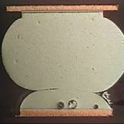 We’ve covered this intriguing project before: the aim is to build a small, cheap module that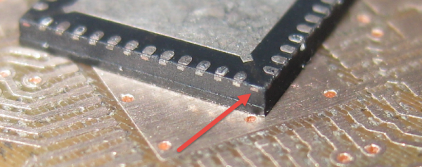
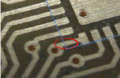 The PCB layout just happens to have a trace exiting right under this conductor. The two aren’t touching, but without solder mask, a bit of melted metal was able to mind the gap and connect the two conductors. [Eric] notes that although the non-pad isn’t documented, it’s easy to prove that it is connected to ground and was effectively pulling down the signal on that trace.








