Chances are you have at least one radio that can receive FM stations. Even though FM is becoming less used now with Internet and satellite options, it still is more popular than the older AM radio bands. FM was the brainchild of an inventor you may have heard of — Edwin Armstrong — but you probably don’t know the whole story. It could make a sort of radio-themed soap opera. It is a story of innovation, but also a story of personal vanity, corporate greed, stubbornness, marital problems, and even suicide. The only thing missing is a long-lost identical twin sibling to turn it into a full telenovela.
Early Days
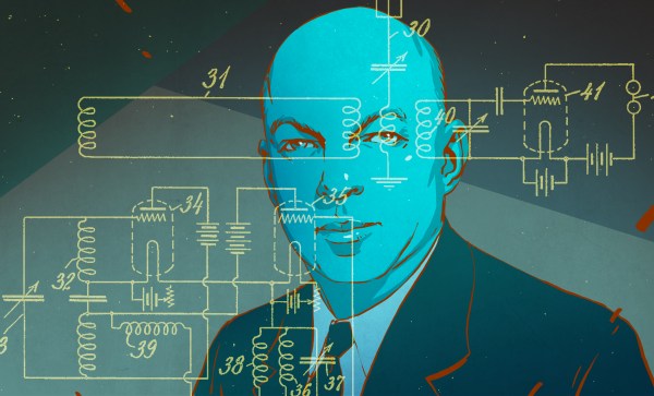
 Armstrong grew up in New York and because of an illness that gave him a tic and caused him to be homeschooled, he was somewhat of a loner. He threw himself into his interest in electric and mechanical devices. By 1909 he was enrolled in Columbia University where professors noted he was very focused on what interested him but indifferent to other studies. He was also known as someone more interested in practical results than theory. He received an electrical engineering degree in 1913.
Unlike a lot of college graduates, Armstrong didn’t go work for a big firm. Instead, he set up a self-financed independent lab at Columbia. This sounded good because it meant that he would own the patents on anything invented there. But it would turn out to be a two-edged sword.