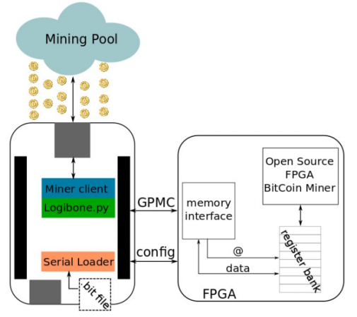
Decoding, Then Cloning An IR Helicopter Toy’s Control Signals

[Mike Field] got his hands on this Syma S107 helicopter with the intention of hacking it. After playing around with it for a while he set out to build his own infrared controller for the toy. It seems there is some protocol information about it published in various forum posts, but he decided it would be more fun to figure it out for himself.

He started off trying to capture the IR signals using Adafruit’s tutorial which has come in handy on a number of other projects. He could get his television remote to register, but not the toy’s controller. This didn’t stop fun, instead he tore open the controller and grabbed a logic sniffer to see what’s being pushed to the IR LEDs. The signals are a bit curious. It seems two different packets are sent with each command which [Mike] thinks is for use with two different models of the toy. In addition to that the frames are not synchronized. But a bit of 10 MHz sampling helped him to figure everything out, and he believes he’s got a more accurate version of the protocol than had previously been discovered. To prove it he developed an FPGA-based controller using VHDL which he shows off in the clip after the break.

Continue reading “Decoding, Then Cloning An IR Helicopter Toy’s Control Signals”

RFID Playlists Plus A QR Code Concept

Here’s another audio playback hack that uses physical tokens to choose what you’re listening to. It uses Touchatag RFID hardware to control iTunes. The concept is very similar to the standalone Arduino jukebox we saw on Wednesday except this one interfaces with your computer and the tags select entire albums instead of just one song. A shell script processes the incoming tag ID from the reader, populates a playlist with all the tracks from the associated album, then executes an AppleScript to launch that playlist. Check out the short demo after the break.

But what really caught our eye is the QR-code reader concept which [Janis] hopes to implement at some point in the future. The computer side of things doesn’t need to be changed, but we love the challenge of putting together an FPGA-based camera to recognize and decode the QR image. Looks like a perfect use for that $10 camera module and it’s FPGA driver!

Continue reading “RFID Playlists Plus A QR Code Concept”

Playing MP3s From An FPGA

Building an audio player is a fun project. It used to be quite a task to do so, but these days the MP3 decoder chips are full-featured which means that if you know how to talk to other chips with a microcontroller you’ve got all the skills needed to pull off the project. But that must have been too easy for [Ultra-Embedded], he decided just to build an MP3 player out of an FPGA.

It’s not quite as difficult as it first sounds. He didn’t have to figure out how to decode the audio compressions. Instead he rolled the Helix MP3 decoder library into the project. It had already been optimized to run on an ARM processor, and since he’s using a RISC soft processor the translation wasn’t tough at all. He’s using a 24-bit stereo DAC chip to bridge the gap between the audio jack and the FPGA output. Clocking that chip with the FPGA isn’t ideal and causes 44.1 kHz audio to run 3% too slow. He says it’s not noticeable, which we believe. But if you try to play along with a song the pitch shift might end up driving you crazy.

If you’d prefer to just stick to the microcontroller based players this one’s small and inexpensive.

Glove-based Touch Screen From A CRT Monitor

Here’s a bulky old CRT monitor used as a touch-screen without any alterations. It doesn’t use an overlay, but instead detects position using phototransistors in the fingertips of a glove.

Most LCD-based touch screens use some type overlay, like these resistive sensors. But cathode-ray-tube monitors function in a fundamentally different way from LCD screens, using an electron gun and ring of magnets to direct a beam across the screen. The inside of the screen is coated with phosphors which glow when excited by electrons. This project harness that property, using a photo transistor in both the pointer and middle finger of the glove. An FPGA drives the monitor and reads from the sensors. It can extrapolate the position of the phototransistors on the display based on the passing electron beam, and use that as cursor data.

Check out the video after the break to see this in action. It’s fairy accurate, but we’re sure the system can be tightened up a bit from this first prototype. There developers also mention that the system has a bit of trouble with darker shades.

Continue reading “Glove-based Touch Screen From A CRT Monitor”

$10 Camera Module For Your Next FPGA Project

Here is [Voelker] showing off his FPGA-based camera hardware. He picked up an ov7670 camera on eBay for about $10 and set to work pulling pixels and processing the images. He’s now able to grab thirty frames per second and push them to his own Java display application. He’s using the Papilio board and if you want to give this a try yourself you might be able to snag a free breakout board (wing) for the unit.

[Voelker’s] approach is to grab each frame, and get it ready for quick serial transmission. The incoming frames are at 640×480 resolution. He scales that down to 80×60 and transmitted at 3M baud. The hardware resources used are actually quite light-weight. He wrote his own modules for transfer and photo processing using very little RAM for downscaling and one 128 byte buffer for data transmission. It sounds like he plans to use the camera to view and detect a line to create his own line-following robot.

Wondering where you’ve seen the ov7670 module before? It’s the part used on the TRAKR robot.

Up Your FPGA Game By Learning From This LCD Control Prototype

[Cesar] recently got a PSP display up and running with his FPGA development board. That’s a nice project, but what we really like is that he set aside a lot of time to show how it’s done every step of the way. This isn’t just a tutorial on that particular screen, but an overview of the skill set needed to get any piece of hardware working.

The screen itself is a Sharp LQ043T3DX02; a 480×272 TFT display with 16 million colors. Not bad for your project but when you start looking into the control scheme this isn’t going to be like using a Nokia screen with an Arduino. It takes twenty pins to control it; Red, green, and blue take sixteen pins, four pins are used for control, the rest are CK, DISP, Hsync, Vsync.

Wisely, [Cesar] designs his own interface board which includes the connector for the ribbon cable. It also has drivers for the screen’s backlight and supplies power to the device. With hardware setup complete he digs into the datasheets. We just love it that he details how to get the information you’re looking for out of this document, and shows his method of turning that first into a flow chart and then into code for the FPGA.

JTAG Dongle Pushes Code To FPGA After Bootup

This gnarly beast has near-magical qualities. [Sprite_TM] patched it together as a dongle which attaches to a JTAG header (we’re fairly certain this is not a standard footprint for that interface though). He uses it to push code to an FPGA after that device boots. Why? Well, there’s several reason, but the most generic answer is that some boards will not boot unless there is a chain of trust that validates the code which will be running.

In this case, [Sprite_TM] is using a knock-off board he acquired from a Chinese supplier. It’s a hardware network terminal (thin client), and as you can see in the video after the break, it works just fine. But that’s pretty boring and he wanted to use it for his own purposes. When he plugs in the dongle and powers up the board the network terminal is nowhere to be found, replaced with the code to play Pac-Man as if were a full arcade cabinet.

The dongle is simply a female DIL header, an ATtiny85, and a flash memory chip. The AVR has a software UART that speaks XSVF, the protocol used to push data to the FPGA. The data to be written is stored in the memory chip, and with that header in place reprogramming the AVR is just a matter of connecting an ISP programmer. Brilliant!

Continue reading “JTAG Dongle Pushes Code To FPGA After Bootup”