FPGA Generated SPDIF Output

[Mike Field] just finished implementing SPDIF generation on an FPGA. SPDIF is an industry standard for transmitting digital audio signals; the acronym stands for Sony/Philips Digital Interconnect Format. It’s been around for more than a decade and since it’s found on most home-audio equipment, building an SPDIF output into your projects may be quite a desirable feature. [Mike] mentions several ideas for this functionality like building high-end test equipment, or providing a high-quality output for electronic instruments.

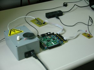
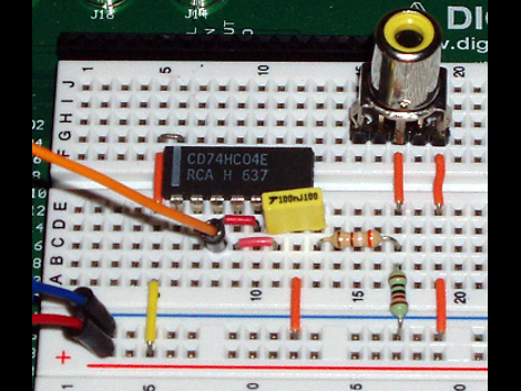
He first jumped into analyzing the specification in order to determine the hardware requirements. Due to some issues with jitter, he found it necessary to use a 100 MHz clock signal. This pushes the jitter down to +/- 5ns of jitter, which he concedes may raise the hackles of audio purists, but does satisfy the published standard. Output requires just one pin of the FPGA and the five components seen above. A hex inverter (74HC04) voltage divider, capacitor, and RCA connector transmit the 0.5V signal to your audio-receiver of choice. Of course, since TOSLINK fiber optic connectors use the same protocol, you could redesign the output and make this an optical connection.

Improved FPGA Synth

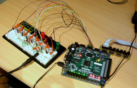
A week or so ago we featured an FPGA MIDI interface. Since then the builder has gone crazy with his FPGA and revised his code to include polyphony and PWM output, and posted a polyphony demo.

In our previous coverage of the build, the synth was monophonic, and the MIDI implementation was pretty shaky. After realizing the hard work was done, [Mich] re-wrote the MIDI interpretation module to keep 8 voices in memory. Now the synth can play 16th note arpeggios at 999bpm.

The original build used 8 pins to output the audio with an R/2R ladder for a digital to analog converter. This didn’t work well with a polyphonic synth (everything was clipped or noisy), so [Mich] moved to PWM output.

Continue reading “Improved FPGA Synth”

FPGA MIDI Interface

Hacking and digital music seem to be very much related arts. This very well built hack goes through the process of creating a MIDI synthesizer using a field programmable gate array (FPGA) and several other components.

A laptop is used as the MIDI interface which runs through a filter and then to the FPGA. This translated signal then goes through a digital to analog converter and finally to the amplifier and speakers. The FPGA is especially interesting as this chip is an array of logic gates that can be programmed however one wants. In this case, the wavetable principle is used to generate sound.

Although this is no Kaossilator yet, this device is a great start and very functional. If you’ve ever wanted to build your own electronic instrument, check out this hack. Also, check out the video after the break! Continue reading “FPGA MIDI Interface”

Use FPGAs The Easy Way With Alien Cortex AV

alien_cortex_av_fpga_board

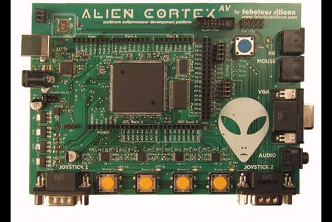
Hackaday reader [Louis] wrote in to call our attention to a neat project over at Kickstarter that he thought would interest his fellow readers. The AlienCortex AV is a pre-built FPGA board from [Bryan Pape] with gobs of ports and a ton of potential. At the heart of the board is an Xilinx PQ208 Spartan 3e 500k FPGA, which can be configured to perform any number of functions. The board sports a healthy dose of analog and digital I/O pins as you would expect, along with PS/2 inputs, VGA outputs, and even a pair of Atari-compatible joystick ports.

The AlienCortex software package allows users to easily load projects into the FPGA, which can run up to four different emulated microcontrollers at once. The software comes with half a dozen pre-configured cores out of the box, with others available for download as they are built. The default set of cores includes everything from a 32-channel logic analyzer, to a quad processor Arduino-sketch compatible machine.

Now, before you cry foul at the fact that he’s emulating Arduinos on a powerful and expensive FPGA, there’s nothing stopping you from creating an army of whatever microcontrollers you happen to prefer instead. We’re guessing that if you can run four Arduinos on this board at once, a good number of PICs could be emulated simultaneously alongside whatever other uC you might need in your next robotics project. A single board incorporating several different microcontrollers at once doesn’t sound half bad to us.

Disco Isn’t Dead: Diy Dance Floor Spotted At Student Parties

Your party is lame if it doesn’t include interactive blinking lights on the dance floor. [Mario] and [Lukas] didn’t want to have lame parties, so they enlisted some fellow students to build an interactive dance floor (translated). The finished party-piece is 4 meters by 2.5 meters (that’s about 13’x8′ for us yanks) and includes 160 lighted squares. But it’s the electronics that really make this a heavy project.

Milled into the underside of the pressboard base are a series of pockets and channels to hold various components. If you look hard enough, you’re going to find eight AVR microcontrollers which control the LEDs, 8 CPLDs to manage the weight sensors which make the floor interactive, and an FPGA and embedded computer to tie everything together. It’s movable, a hit at parties, and so far it seems to hold up to the occasional spilled beverage.

You can’t share a project like this without some video. See it after the break.

Continue reading “Disco Isn’t Dead: Diy Dance Floor Spotted At Student Parties”

FPGA Mandelbrot Fractal Engine

fpga_mandelbrot

[Mike Field] has always been interested in the Mandelbrot Set since he first read about it back in the ‘80s. Having coded it on a Commodore VIC20 back int he day, he always returned to the Mandelbrot set when he wanted to try out some new programming technology.

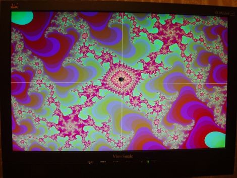
He wanted to delve deeper into the world of FPGAs, so [Mike] figured the best way to do so would be to use one to program a Mandelbrot fractal engine. He started out with a goal of creating a 640×480 Mandelbrot display, but over time, he found that he could push his Nexus 2 FPGA to 800×600. He didn’t stop there, and after tweaking a few things, he was amazed to find that he could push a 1024×768 display from the small board.

He kept a pretty detailed log as he went along, should you be interested in trying your hand at the process as well. Though there is no video of the FPGA in action, there are a few cool pictures showing off his handiwork.

Simple VGA Interface For Tiny FPGA Boards

fpga_vga_adapter

[devb] has been playing around with XESS FPGA boards for ages, and as long as he can remember, they have had built-in VGA interfaces. His newest acquisition, a XuLA FPGA board, doesn’t have any external parts or ports aside from a USB connector. He needed to get video output from the board, so he decided to build a VGA interface himself.

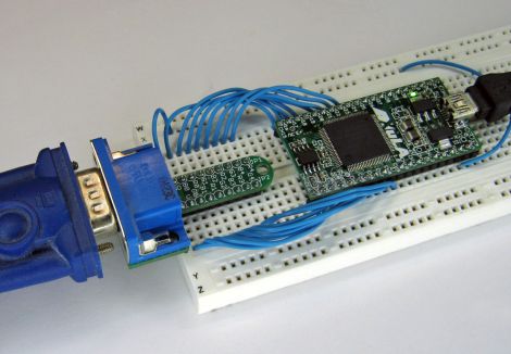
He prototyped a 512-color VGA interface board which worked just fine, but he thought it would be way too cumbersome to use for each and every project. To keep life simple, he designed a small PCB that integrates a VGA connector and all of the resistors he needed to get the signal from the FPGA. His boards plug directly into a breadboard, so only a handful of wires is needed to connect the FPGA to a monitor.

As you can see on his site, the adapter works quite well, allowing the FPGA to put out a crisp 800×600 image with little fuss. [devb] has also posted all of his design files on his site in Eagle format for anyone interested in replicating his work.