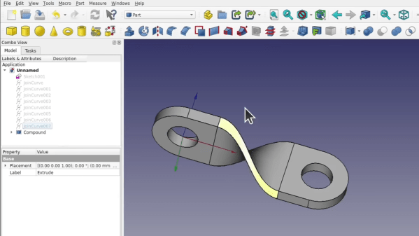
Quick references are handy, but sometimes it’s nice to have a process demonstrated from beginning to end. In that spirit, [Darren Stone] created a video demonstrating how to model a twisted part in FreeCAD, showing the entire workflow of creating the part as a blend of surfaces and curves that get turned into a solid.
FreeCAD is organized using the concept of multiple “workbenches” which are each optimized for different tools and operations, and [Darren] walks through doing the same jobs in a few different ways.
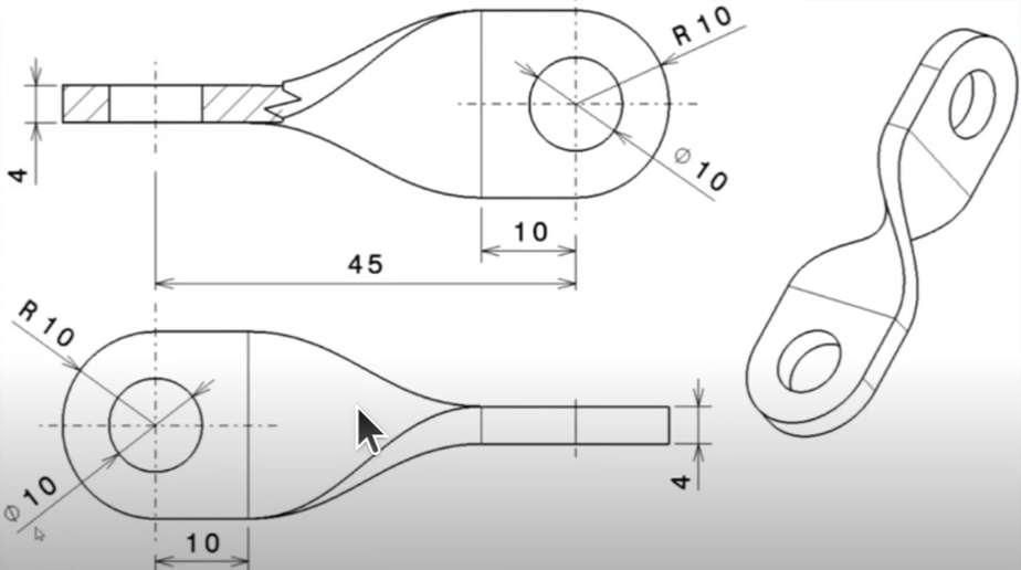
This twisted bracket is a simple part that is nevertheless nontrivial from a CAD perspective, and that makes it a good candidate for showing off the different workbenches and tools.
The video below is also pretty good overall demonstration of what designing a part from a mechanical drawing looks like when done in FreeCAD. As for mechanical drawings themselves, we’ve seen FreeCAD can be used to make those, too.
ChatGPT is an AI large language model (LLM) which specializes in conversation. While using it, [Gil Meiri] discovered that one way to create models in FreeCAD is with Python scripting, and ChatGPT could be encouraged to create a 3D model of a plane in FreeCAD by expressing the model as a script. The result is just a basic plane shape, and it certainly took a lot of guidance on [Gil]’s part to make it happen, but it’s not bad for a tool that can’t see what it is doing.
The first step was getting ChatGPT to create code for a 10 mm cube, and plug that in FreeCAD to see the results. After that basic workflow was shown to work, [Gil] asked it to create a simple airplane shape. The resulting code had objects for wing, fuselage, and tail, but that’s about all that could be said because the result was almost — but not quite — completely unlike a plane. Not an encouraging start, but at least the basic building blocks were there. Continue reading “ChatGPT Makes A 3D Model: The Secret Ingredient? Much Patience”→
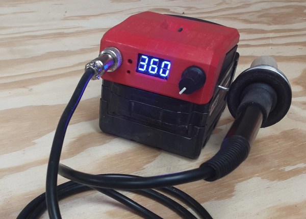
Companies now are looking to secure revenue streams by sneakily locking customers into as many recurring services as possible. Subscription software, OS ecosystems, music streaming, and even food delivery companies all want to lock consumers in to these types of services. Battery-operated power tools are no different as there’s often a cycle of buying tools that fit one’s existing batteries, then buying replacement batteries, ad infinitum. As consumers we might prefer a more open standard but since this is not likely to happen any time soon, at least we can build our own tools that work with our power tool brand of choice like this battery-powered soldering station. Continue reading “Soldering Station Designed Around Batteries”→
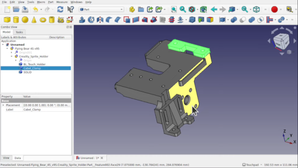
If you’ve tried FreeCAD, you know that it has a daunting number of workbenches and options. [MangoJelly] has a large number of video tutorials on FreeCAD, and the latest one, below, covers working with STEP and STL with the tool.
If you’ve ever wondered why designers like to work with STEP files and not STL, this video answers that question immediately. A part brought in from a STEP file is closer to the original CAD object. It doesn’t have all the operations that make the part up, but it does have proper faces that you can work with like a normal part. The same part imported from STL, however, is one single mesh.
[Neumi] over on Hackaday.IO wanted a simple-to-use way to drive stepper motors, which could be quickly deployed in a wide variety of applications yet to be determined. The solution is named Ethersweep, and is a small PCB stack that sits on the rear of the common NEMA17-format stepper motor. The only physical connectivity, beside the motor, are ethernet and a power supply via the user friendly XT30 connector. The system can be closed loop, with both an end-stop input as well as an on-board AMS AS5600 magnetic rotary encoder (which senses the rotating magnetic field on the rear side of the motor assembly – clever!) giving the necessary feedback. Leveraging the Trinamic TMC2208 stepper motor driver gives Ethersweep silky smooth and quiet motor control, which could be very important for some applications. A rear-facing OLED display shows some useful debug information as well as the all important IP address that was assigned to the unit.
Control is performed with the ubiquitous ATMega328 microcontroller, with the Arduino software stack deployed, making uploading firmware a breeze. To that end, a USB port is also provided, hooked up to the uC with the cheap CP2102 USB bridge chip as per most Arduino-like designs. The thing that makes this build a little unusual is the ethernet port. The hardware side of things is taken care of with the Wiznet W5500 ethernet chip, which implements the MAC and PHY in a single device, needing only a few passives and a magjack to operate. The chip also handles the whole TCP/IP stack internally, so only needs an external SPI interface to talk to the host device.
When designing even a reasonably simple 3D-printable part, you need to account for all the supports it will require to print well. Strategic offsetting, chamfering, and filleting are firmly in our toolkits. Over time we’ve learned to dial our settings in so that, hopefully, we don’t have to fumble around with a xacto knife after the bed has cooled down. On Twitter, Chris shows off his foldable 3D print experiments (nitter) that work around the support problem by printing the part as a single piece able to fold into a block as soon as you pop it off the bed.
The main components of this trick seem to be the shape of the place where the print will fold, and the alignment of bottom layer lines perpendicular to the direction of the fold lines. [Chris] shows a cross-section of his FreeCad design, sharing the dimensions he has found to work best.
Of course, this is Twitter, so other hackers are making suggestions to improve the design — like this sketch of a captive wedge likely to improve alignment. As for layer line direction alignment, [Chris] admits to winging it by rotating the part in the slicer until the layer lines are oriented just right. People have been experimenting with this for some time now, and tricks like these are always a welcome addition to our toolkits. You might be wondering – what kinds of projects are such hinges useful for?
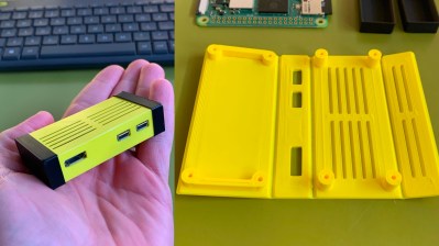
The example Chris provides is a Eurorack rail segment — due to the kind of overhangs required, you’d be inclined to print it vertically, taking a hit to the print time and introducing structural weaknesses. With this trick, you absolutely don’t have to! You can also go way further and 3D print a single-piece foldable Raspberry Pi Zero case, available on Printables, with only two extra endcaps somewhat required to hold it together.
Foldable 3D prints aren’t new, though we typically see them done with print-in-place hinges that are technically separate pieces. This trick is a radical solution to avoiding supports and any piece separation altogether. In laser cutting, we’ve known about similar techniques for a while, called a “living hinge”, but we generally haven’t extended this technique into 3D printing, save for a few manufacturing-grade techniques. Hinges like these aren’t generally meant to bend many times before they break. It’s possible to work around that, too — last time we talked about this, it was an extensive journey that combined plastic and fabric to produce incredibly small 3D printed robots!
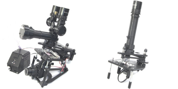
What do you get when you cross a day job as a Medical Histopathologist with an interest in 3D printing and programming? You get a fully-baked Open Source microscope, specifically the Portable Upgradeable Modular Affordable (or PUMA), that’s what. And this is no toy microscope. By combining a sprinkle of off-the-shelf electronics available from pretty much anywhere, a pound or two of filament, and a dash of high quality optical parts, PUMA cooks up quite possibly one of the best open source microscopy experiences we’ve ever tasted.
GitHub user [TadPath] works as a medical pathologist and clearly knows a thing or two about what makes a great instrument, so it is a genuine joy for us to see this tasty project laid out in such a complete fashion. Many a time we’ve looked into an high-profile project, only to find a pile of STL files and some hard to source special parts. But not here. This is deliberately designed to be buildable by practically anyone with access to a 3D printer and an eBay account.
The project is not currently certified for medical diagnostics use, but that is likely only a matter of money and time. The value for education and research (especially in developing nations) cannot really be overstated.
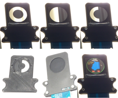
A small selection of the fixed and active aperture choices
The modularity allows a wide range of configurations from simple ambient light illumination, with a single objective, great for using out in the field without electricity, right up to a trinocular setup with TFT-based spatial light modulator enabling advanced methods such as Schlieren phase contrast (which allows visualisation of fluid flow inside a live cell, for example) and a heads-up display for making measurements from the sample. Add into the mix that PUMA is specifically designed to be quickly and easily broken down in the field, that helps busy researchers on the go, out in the sticks.
The GitHub repo has all the details you could need to build your own configuration and appropriate add-ons, everything from CAD files (FreeCAD source, so you can remix it to your heart’s content) and a detailed Bill-of-Materials for sourcing parts.
We covered fluorescence microscopy before, as well as many many other microscope related stories over the years, because quite simply, microscopes are a very important topic. Heck, this humble scribe has a binocular and a trinocular microscope on the bench next to him, and doesn’t even consider that unusual. If you’re hungry for an easily hackable, extendable and cost-effective scope, then this may be just the dish you were looking for.
 FreeCAD is organized using the concept of multiple “workbenches” which are each optimized for different tools and operations, and [Darren] walks through doing the same jobs in a few different ways.
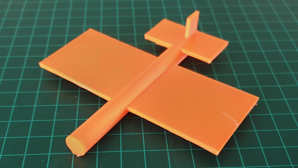
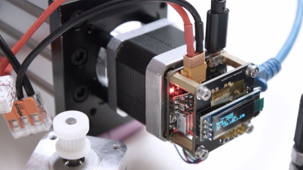
 making uploading firmware a breeze. To that end, a USB port is also provided, hooked up to the uC with the cheap CP2102 USB bridge chip as per most Arduino-like designs. The thing that makes this build a little unusual is the ethernet port. The hardware side of things is taken care of with the
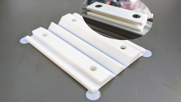
 The example Chris provides is a Eurorack rail segment — due to the kind of overhangs required, you’d be inclined to print it vertically, taking a hit to the print time and introducing structural weaknesses. With this trick, you absolutely don’t have to! You can also go way further and 3D print a single-piece foldable