Hacklet 97 – Camera Projects

We last covered camera projects way back in Hacklet #11. A ton of camera projects have been added to Hackaday.io since then. While the rest of the world is taking selfies, hackers, makers, and engineers have been coming up with new ways to hack their image capture devices. This week on the Hacklet, we’re taking a look at some of the best camera projects on Hackaday.io!
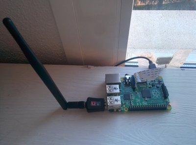
pixelzFirst up is [aleksey.grishchenko] with PiXel camera. PiXel is a camera and a live video display all in one, We wouldn’t exactly call it high-definition though! A Raspberry Pi uses its camera module to capture images of the world. [Aleksey] then processes those images and displays them on a 32 x 32 RGB LED matrix. This matrix is the same kind of tile used in large outdoor LED signs. The result is a surreal low resolution view of the world. Since the Pi, batteries, and camera all hide behind the LED matrix, there is an unobstructed view of the world around you. [Aleksey] used  [Henner Zeller’s] matrix library to make this hack happen.

imager
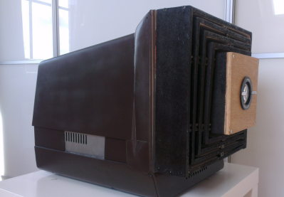
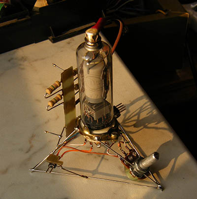
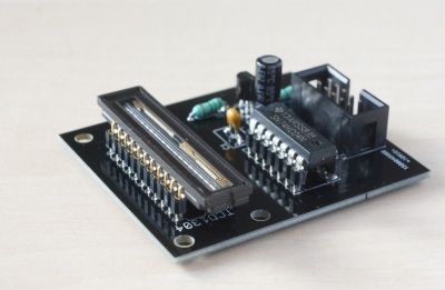
Next up is [Esben Rossel] with Linear CCD module. [Esben] is building a Raman spectrometer, much like 2014 Hackaday Prize finalist [fl@C@] with his own ramanPi. The heart of a spectrometer is the linear image capture device. Both of these projects use the same TCD1304 linear CCD. Linear Charge Coupled Devices (CCDs) are the same type of device used in flatbed document scanners. The output of the CCD is analog, so an ADC must be used to capture the data. [Esben] is using an STM32F401RE on a Nucleo board as the control logic. The ST’s internal ADC converts the analog signal to digital. From there, it’s time to process all the spectra.

wiimote-cam[Chiprobot] brings the classic Wii remote camera to the internet of things with
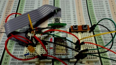
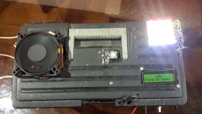
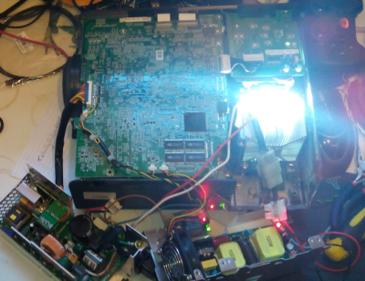
ESP8266 meets Wii Mote Camera. The Wii remote uses a camera which doesn’t output images, instead it plots the location of up to four IR LEDs. Normally these LEDs are located in the poorly named sensor bar that is sold with the Wii. Hackers have been using these cameras in projects for years now. [Chiprobot] paired his camera with the modern classic ESP8266 WiFi module. The ‘8266 is programmed to read data from the camera’s I2C bus. It then sends the data as an SVG request to the W3C website. W3C returns a formatted image based on those coordinates. The resulting image is a picture of the IR LEDs seen by the camera. Kind of like sending your negatives out to be developed.

photobooth
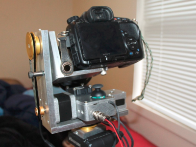
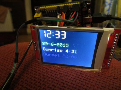
Finally, we have [GuyisIT] with Raspberry Pi Photobooth. Photo booths are all the rage these days. First it was weddings, but now it seems like every kids party has one. [GuyisIT] didn’t rent a booth for his daughter’s birthday, he built one using his Raspberry Pi and Pi camera. The project is written in python, based upon [John Croucher’s] code. When the kids press a button, the Pi Snaps a series of pictures. The tiny Linux computer then joins and rotates the images while adding in some superhero themed graphics. Finally the Pi prints the image on to a photo printer. The biggest problem with this hack is re-triggering. The kids loved it so much, they kept pressing the big red button!

If you want to see more camera projects, check out our updated camera projects list! If I missed your project, don’t be shy! Just drop me a message on Hackaday.io. That’s it for this week’s Hacklet. As always, see you next week. Same hack time, same hack channel, bringing you the best of Hackaday.io!

Hacklet 93 – Robotics Toolkit And ESP8266 Packet Injection

You never know where a hack will take you. Sometimes a simple project will take on a life of its own and become a huge software framework. Other times, a reading blog can turn into a weekend project. Hackaday.io is the place to upload every project, big, small, or somewhere in between. This week on the Hacklet, we’re taking a look at two projects – one big, one small.

wifi1[Rand Druid] recently spent a Weekend on the Dark Side, creating an ESP8266 packet injector. The project started when [Rand] read about [Kripthor’s] deauth packet injection attacks right here on Hackaday. He initially created the WiFi denial of service throwie mentioned in the article. The basic Bill of Materials (BOM) for this device is an ESP8266 module, a DC/DC converter, a 9V battery, connectors, and a few resistors. This worked well, but some devices (most notably [Rand’s] son’s Android Phone) would disconnect and reconnect so quickly the attack had no practical impact.


double-wifi[Rand] fixed the problem by adding a second ESP8266 module. The first is the listener. It listens for WiFi access points. Once an AP is found, it sends this information to the second jammer” module via a unidirectional single line serial link. The jammer module pumps out deauth packets at full speed. He even managed to create a single executable which performs as both listener and jammer. At boot, the software sends out a series 0xFF bytes through the serial port. The listener has its serial transmit pin directly connected to the jammer’s serial receive line. When the jammer receives the 0xFF bytes, it jumps into the correct function. This was more than enough to kick that pesky Android phone off the network. As with the original article, we have to stress that you should only use modules like these for testing on your own equipment. Be careful out there folks!


bowler[Kevin Harrington] loves robots, but hates reinventing the wheel every time he creates a new machine. He’s built BowlerStudio: A robotics development platform to combat this problem. BowlerStudio was a semifinalist in the 2015 Hackaday Prize. BowlerStudio is a soup-to-nuts platform for creating all sorts of robots. [Kevin] has integrated Computer Aided Design (CAD), 3D modeling, kinematics, machine vision, and a simulation engine complete with physics modeling into one whopper of a software package. To prove how versatile the system is, he designed a hexapod robot in the CAD portion of the program. The robot then taught itself to walk in the simulation. Once the design was 3D printed, the real robot walked right off the bread board. [Kevin] linked the hardware and software with DyIO, another of his projects.

BowlerStudio is a huge boon for just about any robotics hacker, as well as educators. An entire curriculum could be created around the system. Thanks to its Java roots, BowlerStudio is also a multi-platform. [Kevin] has binaries ready to go for Windows, Mac, and Ubuntu.

The newest feature in BowlerStudio is JBullet. JBullet is a Java port of the Bullet physics library. Physics means that important real world effects like gravity and surface friction can now be added to simulations. In [Kevin’s] own words “This project is starting to feel more and more like a game engine targeted towards designing robotics and engineering tools.”

 That’s it for this week’s Hacklet. As always, see you next week. Same hack time, same hack channel, bringing you the best of Hackaday.io!

Hacklet 92 – Workbenches And Toolboxes

Everyone needs a place to work. While some of us have well equipped labs with soldering stations, oscilloscopes, and a myriad of other tools, others perform their hacks on the kitchen table. Still, some hackers have to be on the go – taking their tools and work space along with them on the road. This week’s Hacklet is all about the best toolbox and workbench projects on Hackaday.io!

worktableWe start at the top – in this case, a bench top. [KickSucker] created Mondrian Inspired Work Table as a multi-use tabletop for all kinds of projects. Rather than slap down a piece of plywood, [KickSucker] took a more artistic route. Piet Mondrian was a dutch artist known for painting irregular grids of black and white lines. He’d fill a few of the rectangles up with primary colors, but leave most of them white. Between different off-cuts of wood, and colorful bits of skateboard deck [KickSucker] had the makings of an awesome work surface. The frame of the bench is an IKEA expedite shelf unit. The frame is made from MDF, with the offcuts laid on top of it. The fun part was arranging all the pieces to make lines and colors. The result is a great custom work table, and a heck of a lot less wood scraps lying around the shop. That’s a double win in our book!

toolboxNext up is [M.Hehr] with Portable Workbench & mini Lab. [M.Hehr] has wanted a portable electronic workstation for years. We’re betting he’s seen a few of them here on the blog. While cleaning up the lab before Christmas, [M.Hehr] found a couple of wooden IKEA boxes. Each box held some drawers. An idea formed in [M.Hehr’s] head. It was time to put the plan in motion! The boxes were attached and hinged. Custom brackets were cut on a Shapeoko 2 router. Everything – even the screws were recycled. [M.Hehr] created a perfect space for each tool, ensuring that things won’t end up in a tangled mess when the box is carried around. We really love the retractable power point and custom-made power supply!

roadcaseNext we’ve got [Tim Trzepacz] with Musician’s Road Box with 9 space rack. [Tim’s] sister [Tina] was playing a lot of music on the road, and needed a way to organize her gear. There are plenty of commercial solutions for this, but [Tim] decided to roll the perfect solution. He designed a plywood box with a 9U rack. [Tina’s] mixer and backing sound sources were located on the top, while effects and other modules were located in the rack. [Tim] spent a good amount of time designing the box. He was able to get the cut list down to a single piece of plywood, with room to spare. This is perfect for a 4′ x 8′ router like the ShopBot. When it comes time to hit the road, the case seals up to a rugged package. Standard roadcase corners and twist-latches finish this awesome piece.

boxtopFinally we have [Géllo] with protoBox. [Géllo] is into induction heating, which requires a Zero Voltage Switching (ZVS) flyback driver. ProtoBox started life as a place for [Géllo] to store his ZVS. It has evolved to become a small portable electronics lab. [Géllo] powers the box with a set of lithium-ion batteries sourced from old laptops. This particular ZVS design is plenty powerful enough to heat metal red hot, or create some nice arcs. [Géllo] added an Arduino Mega, a Bluetooth radio, and a 2×16 character LCD. The system is controlled with relays. A bluetooth enabled smartphone can be used to enable or disable any feature. [Géllo’s] assembly techniques are a bit scary, especially considering the fact that this is a high power design. However, this is a great proof of concept!

If you want to see more workbench and toolbox projects, check out our new workbench and toolbox list! If I missed your project, don’t be shy! Just drop me a message on Hackaday.io. That’s it for this week’s Hacklet. As always, see you next week. Same hack time, same hack channel, bringing you the best of Hackaday.io!

Hacklet 88 – Projector Projects

Everyone loves a big screen TV. Back in the old days, anything over 27 ” was considered big. These days if you’re not sporting at least 50″, you’ll end up with display envy. One thing hasn’t changed though, those who want to go really, really big get into projectors. Hacking and projectors seem to go hand in hand. Anyone else remember those old DIY projection setups where the user would put their TV in a box upside down? This week’s Hacklet is all about projector hacks!

hushWe start with [Chaz] with Projector Hush Box . [Chaz] had a good projector, but still found himself with a problem. Projectors generate a lot of heat, which is dissipated via a fan. For whatever reason, projector companies seem to pick the loudest fans available. [Chaz’s] solution is to put the projector inside a box. Done right, this makes for a quiet projector. Done wrong, it makes an oven. [Chaz] projector hasn’t caught fire yet, so we think he did it right. Two quiet and efficient PC fans direct air through the box, and around baffles which keep the noise down. An anti-reflective coated glass window lets the light out but keeps the noise in. Sound deadening foam helps cut the sound down even further.

led-projNext up is [ric866] with 100w LED projector conversion. The killer with projectors these days are the bulbs. In some cases it’s more cost-effective to buy a new projector than to replace the bulb in an aging one. That’s how [ric866] ended up with a pair of old NEC projectors – one with a working bulb, and one without. Bulbs for this model aren’t cheap at £100. [ric866] found a cheap replacement in a 100 Watt LED. The LED in question only cost £8.99 from everyone’s favorite auction site. LEDs may be efficient, but anyone who’s played with powerful LEDs can tell you they still get hot. [ric866] had to cut up the projector’s case a bit to fit in a heat sink and fan. He also had to spend some time bypassing the various case interlock switches. The final products color calibration looks to be a bit off, but not too shabby for a quick mod!

baffle[Tom_VdE] is serious about recycling. He isn’t one to let an old laptop go to waste when it can be turned into a projector! Remember the “TV in a box” kit we mentioned up in the title? This is the modern version of that same idea. [Tom] tore down the laptop’s LCD and placed it in a CRT monitor case with the appropriate lenses. A setup like this needs length, and focus adjustments. [Tom] managed all that by building a collapsible baffle out of plywood. A build like this needs a lot of light, so [Tom] is using a 100 Watt LED (or two). A water cooling system will keep the LED’s from melting down. [Tom] is still in the prototype phase, but we can’t wait to see his first movie night with this upcycled laptop.

sensorcalFinally, we have [Alex] who built Automatic projector calibration, project #161 on Hackaday.io. [Alex] took his inspiration from [Johnny Chung Lee] to build a system which can map a projector to any angle, size, or position. The secret is phototransistors embedded in the corners of a rectangular piece of foamboard. An Arduino reads the phototransistors while the projector runs a calibration routine. [Alex] switched over to a scanning line from [Johnny’s] original binary pattern. The scan isn’t quite as fast as the binary, but it sure looks cool. Once the positions of the sensors are known, it’s just a matter of mapping the entire screen to a smaller piece of real estate. Toss in a few neat transitions, and you’ve got an awesome demo.

If you want to see more projector projects, check out our new projector project list! If I missed your project, don’t be shy, just drop me a message on Hackaday.io. That’s it for this week’s Hacklet. As always, see you next week. Same hack time, same hack channel, bringing you the best of Hackaday.io!

Hacklet 86 – Time-lapse Projects

“If I could save time in a bottle…” it’s not just an old song, it’s a passion for many photography hackers. Time-lapse photography is a way to show the movement of time through still images. These images are animated into what essentially is a video recorded at a super low frame rate. We’re talking one frame per minute or slower in some cases! The camera doesn’t have to be still for all this, but any motion must be carefully controlled. This has led hackers, makers, and engineers to create a myriad of time-lapse rigs. This week’s Hacklet is all about some of the best time lapse projects on Hackaday.io!

rig-1We start with [Swisswilson] and the simply named Timelapse rig. To say this rig is beefy would be an understatement. All the aluminum parts, with the exception of the gears, were machined by [Swisswilson]. Two Nema-23 Nema-17 motors are controlled by Sparkfun Easy Stepper Drive boards, while an Arduino Micro serves as the controller. The electronics are all housed in a sturdy box which also serves as a remote control. A joystick allows pan and tilt to be manually controlled. The bombproof construction is definitely a help here, as [Swisswilson] is using this rig with DSLR cameras. Combined with a lens, these setups can reach a pound or two.


pilapseNext up is [minWi], who put their script-foo to work with raspilapse. Raspilapse automates the entire process of taking photos, assembling them into a movie, and uploading to YouTube. The hardware is a Raspberry Pi Model B, with a RasPi Camera. The Pi shoots images then uploads them to a Virtual Private Server (VPS). [minWi] used an external server to save wear and tear on the Pi’s SD storage card. At the end of the day, the VPS uses ffmpeg to assemble the images into a video, then uploads the whole thing to YouTube. We’re betting that with a few script mods, this entire process could be run on a Raspberry Pi 2. If you’re really worried about the SD card, a USB flash drive could be used.


SunriseSunsetRig[Andyhull] takes us down to one frame per day with Sunset and Sunrise camera controller. [Andy] wanted to get shots of the sunrise every day. Once converted to a video, these shots are great for documenting the passing of the seasons. He used a Canon point and shoot camera along with the Canon Hack Devleoper’s Kit (CHDK) for his camera. The camera has its own real-time clock, and with CHDK, it can be programmed to shoot images at sunrise. The problem is power. Leaving the camera on all the time would quickly drain the batteries. Arduino to the rescue! [Andy] programmed an Arduino Pro Mini to turn the camera on just before sunrise, then shut it back down. The standby power of a sleeping ATmega328 is much lower than the camera’s, leading to battery life measured in weeks.


podFinally, we have [caramellcube] who added data to their time-lapse photos with Portable Observation Device (POD). POD was conceived as a device to aid paranormal investigators. The idea was to have a device that could take images and record data at a set interval from within a locked room. Sounds like a job for a Raspberry Pi! [caramellcube] started with Adafruit’s Raspberry Pi-based touchscreen camera kit. From there they added a second board controlled by an Arduino Nano. The Nano reads just about every sensor [caramellcube] could fit, including humidity, air pressure, magnetic field strength, acceleration, light (4 bands), sound, and static charge. The Nano allows [caramellcube] to connect all those sensors with a single USB port on the Pi. We’re not sure if [caramellcube] has found any ghosts, but we’re sure our readers can think of plenty of uses for a device like this!

If you want to see more time-lapse projects, check out our new time-lapse projects list! If I missed your project, don’t be shy, just drop me a message on Hackaday.io. That’s it for this week’s Hacklet. As always, see you next week. Same hack time, same hack channel, bringing you the best of Hackaday.io!

Hacklet 85: Alternative Audio Amplifiers

When you think of amplifiers, you’re probably thinking of audio or some big ‘ol power amps for radios. While interesting, there are some very interesting ‘alternative’ amplifiers floating around hackaday.io that are more than just power amps, and exceedingly useful, to boot.

1601181393316190625[Ronald] bought an XMS amplifier a few years ago, and although it worked well, every time he changed the input, the loudness had to be toggled. One thing led to another, and he realized this amplifier had a four-channel audio processor that could be controlled by I2C. This was the beginning of his Network Amplifier.

Inside the box is a Raspberry Pi that controls a PT2314-based amplifier. Also included is a 2×16 character LCD, a few LEDs, switches, and a rotary encoder.  There was an Android app that controlled the amplifier, but this was discarded for a better looking web-based solution. Now [Ronald] has every audio source available over WiFi.

973501443636885535What if you want an audio amplifier without a speaker? Wait, what? That’s what [DeepSOIC] is doing with his experiments in ion wind loudspeakers.

‘Ion wind lifters’ have been around for decades now, mostly in the labs of slightly off-kilter people who believe this is the technology aliens are using to visit earth. Nevertheless, ion wind lifters produce an airflow, and if you make that wind variable, you get sound. Pretty cool, huh?

The amplifier for this project uses a tube to modulate kilovolt supply through the ion ‘blower’. Does it work? Sure does. [DeepSOIC] got a piece of 0.2 mm nichrome wire to discharge ions into the air, after which the ions drift into the second electrode. The result is sound, and the entire project is built deadbug style. It really doesn’t get cooler than this.


2981611414932529525Continuing with the tube amp trend, [Marcel] built the cheapest little tube amp around.

The design of an audio tube amp is fairly simple business. First, you start with a big ‘ol transformer, and rectify the AC into DC. This gets fed into a preamp tube, and this is fed into a bigger power tube.

In about 50 years of development, tube designers had the technology down pat by the mid 1950s, and triode/pentode tubes were created. This allowed tube designers to condense two amplifier stages into a single tube. While this setup was usually used for cheap, toy-like electronics, you can still buy the ECL82 tube today.

[Marcel] took one of these tubes, added a rectifier tube, transformer, and big cap to create the simplest possible tube amp. Use it for guitars, use it for hi-fis, it’s all the same. It’s not going to sound great, but it is a very easy amp to build.

All of these interesting audio amplifier projects are curated on this new list! If you have a build that amplifies sound in an interesting way, don’t be shy, just drop [Adam] a message on Hackaday.io and he’ll add it. That’s it for this week’s Hacklet. As always, see you next week. Same hack time, same hack channel, bringing you the best of Hackaday.io!

Hacklet 83 – Tiny Robot Projects

Hackers, makers, and engineers have been hacking on robot projects since the era of clockwork mechanics. Any robot is a cool project, but there is something particularly attractive about small ones. Maybe it’s the skill required to assemble them, or perhaps it’s the low-cost. Either way, there are lots of palm-sized robot projects on Hackaday.io. This week on the Hacklet, we’re going to highlight a few of them!

tinyrobot2We start with the granddaddy of them all, [shlonkin] and Tiny robot family. [Shlonkin] built line following robots that can hide under a US half-dollar coin. The robots are simple circuits – an ATtiny85 with an LED and pair of phototransistors. The code is provided both in Arduino’s wiring, and in straight C++. Two coreless motors, normally used in cell phones vibrators or quadcopters, provide the locomotion. These robots only know one thing – moving forward and following a line. They do it well though! We love this project so much that we hosted a tiny robot workshop at the 10th anniversary back in 2014.

toteWhen it comes to tiny walking robots, [Radomir Dopieralski] is the king. Many of his projects are small biped, quadruped, or even hexapod robots. He’s done things with 9 gram nano servos that we thought were impossible. Tote, an affordable spider robot, is his latest creation. Tote is a four-legged bot utilizing 12 9 gram servos. [Radomir] created a custom PCB for Tote, which acts as a carrier for its Arduino Pro Mini Brain. This robot is easily expandable – [Radomir] has experimented with the Teensy 3 series as well. Controlling the robot can be anything from an ESP8266 to an infrared remote control.

botbot[Alan Kilian] may well have the ultimate tease project with Hand-wound inductors for a tiny robot. [Alan] was using some tiny GM-10 motors on his micro-bot. The motors didn’t have inductance for the locked-antiphase drive controller. His solution was to wind some coils to provide a bit of added inductance. The mod worked, current consumption dropped from 116 ma to about 6 ma. We want to know more about that ‘bot though! It’s controlled by a Megabitty, [Monty Goodson’s] ATmega8 controller board from sometime around 2003. The lilliputian board has been very popular with the nano sumo crowd. Other than the controller, motors, and the plywood frame, [Alan] has left us guessing about his robot. If you see him, tell [Alan] to give us more info on his micro robot’s design and construction!


espbot
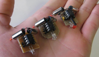
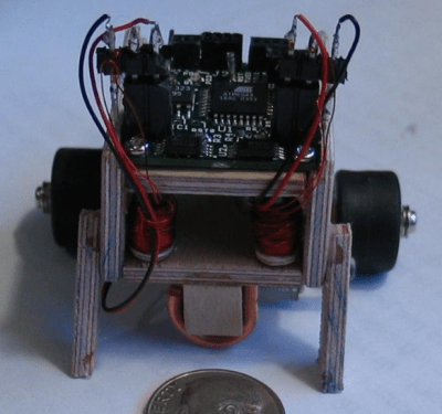
[Ccates] jumped on the tiny robot bandwagon with Tiny wi-fi robot. Rather than go with an Arduino for control, [Ccates] grabbed the popular ESP-8266 WiFi module. The construction of the bot is inspired by [shlonkin’s] tiny robot family up above. This bot is controlled by the Xtensa processor embedded in the ESP-8266. Since it only drives forward, it only takes two GPIO pins to control the transistors driving the motors. Even the diminutive ESP-01 module has enough I/O for that. We’d love see some sensors and a full H-bridge on this micro beastie!


If you want to see more palm-sized robot projects, check out our new tiny robot projects list! These ‘bots are small, so I may have missed yours. If that’s the case, don’t be shy, just drop me a message on Hackaday.io. That’s it for this week’s Hacklet. As always, see you next week. Same hack time, same hack channel, bringing you the best of Hackaday.io!