ContactKey: A Portable, Battery-powered Phonebook

contactKey

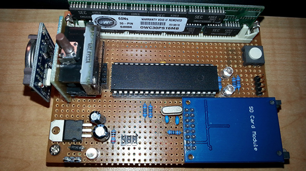
Although it’s still a prototype, [Russell] tipped us off to his battery-powered device for storing your contacts list: ContactKey. (Warning: Loud sound @ beginning). Sure, paper can back up your contact information, but paper isn’t nearly as cool to show off, nor can it receive updates directly from your Android. The ContactKey displays a contact’s information on an OLED screen, which you can pluck through by pressing a few buttons: either ‘Up,’ ‘Down,’ or ‘Reset’. Although the up/down button can advance one contact at a time, holding one down will fly through the list at lightning speed. A few seconds of inactivity causes a timeout and puts the ContactKey to sleep to conserve battery life.

This build uses an ATMega328 microcontroller and an external EEPROM to store the actual list. [Russell] wrote an Android app that will sync your contact list to the ContactKey over USB via an FTDI chip. The microcontroller uses I2C to talk to the EEPROM, while an OLED display interfaces to the ATMega through SPI. We’re looking forward to seeing how compact [Russell] can make the ContactKey once it’s off the breadboard; the battery life for most smartphones isn’t particularly stellar. Phones of the future will eventually live longer, but we bet it won’t be this one.

Continue reading “ContactKey: A Portable, Battery-powered Phonebook”

Haunted Dollhouse Microcontroller Networking For World Maker Faire

master-slave-networks

It’s pretty awesome to get see the number of projects presented at World Maker Faire. But we still love digging into the gritty details that only an in-depth build post can deliver. Here we get both. You can see the circuits pictured above in the Circuit Castle exhibit at WMF this weekend, and you can read about how the microcontroller network was built in [Jim’s] article.

As the title states, this is a network built for a dollhouse. Each slave device performs a different task; adding color, sound, motion, and interactivity using some sensors.  The post discusses the i2c (or TWI to get around licensing issues as [Jim] mentions) communications used to talk to the ATtiny85 chips on the slave boards. Because the eight-pin package leaves few I/O pins to work with an ATtiny84 was also added. It brings 14-pins to the party, including multiple ADC inputs for reading sensors.

If this ends up being too much of a read for you jog to the “Update 9/17/13” to get the general overview of progress. Like any project on a timeline, not everything works quite as well as they would have liked it to. But it’s the journey that makes something like this so fun — a fully working project would signal an end to the enjoyment, right?

[via Workshop 88]

Turning Cheap Voltmeters Into I2C Displays

Voltmeter I2C Displays

[Tom] needed 8 displays for a project. He wanted to to control them over I2C, and was trying to reduce cost. Some vendors make I2C controllable seven segment displays, but they cost about $10 each. [Tom] figured he could hack cheap voltmeters to get the same results for about $3 a pop.

The voltmeters that [Tom] bought used a 8 bit STM8S003F3P6 microcontroller. He reverse engineered the device and re-created the schematic to find out where the I2C and programming pins would be. Then he hooked it up to a STM8 Discovery development board, which has an integrated programmer.

With the hardware figured out, it was time for new firmware. Fortunately, [ba0sh1] had already written firmware for a similar purpose which could easily be adapted. The code implements a software I2C slave, which reads data off the bus and displays it. It’s all available on Github.

The end result is a I2C controlled display for a third of the cost. Next time you need a bunch of these in a project, consider picking up some cheap voltmeters.

Fix A Keyboard’s Firmware With Trial, Error, And I2C

eepromKeyboardFlash

If the media shortcut keys on your keyboard don’t function correctly due to outdated firmware, the manufacturer may recommend you ship it to them for an update. [Alvaro] didn’t care to wait that long, so he cracked it open and taught himself how to mod the EEPROM. The result is a well-documented breakdown of sorting out the keyboard’s guts. Inside he finds a USB hub, which he ignores, and the keyboard controller chip, which he attacks. Two data sheets and a schematic later, [Alvaro] breaks out the logic analyzer to compare physical key presses to the keypad codes they output.

He dumps the entire EEPROM and follows up with a quick flash via I2C to change the “next song” key to instead output the letter “a”. That seems to work, so [Alvaro] combs through an HID USB usage table for some codes and has to guess which ones will properly control Spotify. He converts the media keys from “scan next” and “scan previous” to “rewind” and “fast forward.” Problem solved.

[Alvaro] had zero knowledge of keyboards prior to opening this one up. If you aren’t already taking things apart to see how they function and how to fix them, hopefully his success will persuade you to explore and learn about those “black boxes” in your home. And, if you’ve never used I2C before—or think it might be the name of a boy band—head over to [Kevin’s] tutorial on bitbanging I2C by hand.

Designing A Pressure Sensitive Floor

ccm_activefloor8

[Sean] and his team at Adobe were asked to build “something new” for the Children’s Creativity Museum in San Francisco, so in several months they managed to build a digital/physical environment for kids called “Sense It”.

Part of this project involved designing and building a pressure-sensitive electronic floor which could detect if children were sitting, walking or running. As a camera based detection system couldn’t give them the type of precision they wanted, [Sean] decided to use pressure-sensitive resistors placed under MDF panels.

There are a total of twenty-one 2’x4′ tiles, each one including 8 pressure-sensitive resistors and an ATtiny84 based platform. All the microcontrollers digitize their 8 sensor signals and send their conversion results to a beaglebone over a shared i2c bus in a RJ45 CAT5 cable. As it is [Sean]’s first project, we will cut him some slack but several design mistakes have been made in our opinion:

  • Using i2c instead of RS485 / CAN for long distance data transmission
  • Digitizing the sensor voltages so far from them, as noise is added before the ADC
  • Sending the +5V required by the ATtiny in the RJ45 cable instead of a higher voltage (which would involve putting an LDO on the platforms)
  • Separating the digital and analog ground planes as the platform current consumption is low and transmission speeds slow

But the children who can now play with the complete system certainly won’t care. And you… what do you think of [Sean]’s work? Don’t hesitate to let us know in the comment section below.

Bitbanging I2C By Hand

I2C

Play around with electronics long enough, and eventually you’ll run into I2C devices. These chips – everything from sensors and memory to DACs and ADCs – use a standardized interface that consists of only two wires. Interacting with these devices is usually done with a microcontroller and an I2C library, but [Kevin] wanted to take that one step further. He’s bitbanging I2C devices by hand and getting a great education in the I2C protocol in the process.

Every I2C device is controlled by two connections to a microcontroller, a data line and a clock line. [Kevin] connected these lines to tact switches through a pair of transistors, allowing him to manually key in I2C commands one bit at a time.

[Kevin] is using a 24LC256 EEPROM for this demonstration, and by entering a control byte and two address bytes, he can enter a single byte of data by hand that will be saved for many, many years in this tiny chip.

Of course getting data into a chip is only half of the problem. By altering the control byte at the beginning of an I2C message by one bit, [Kevin] can also read data out of the chip.

This isn’t [Kevin]’s first experimentation in controlling chips solely with buttons. Earlier, we saw him play around with a 595 shift register using five push buttons. It’s a great way to intuit how these chips actually work, and would be an exceptional learning exercise for tinkerers young and old,

Continue reading “Bitbanging I2C By Hand”

PCA9517 I2c Translator A Perfect Companion For Raspberry Pi Hardware Add-ons

The rig pictured above works as an Internet connected temperature sensor which sends [Zaion] an email with a graph of the change over time. This in itself is interesting, but one part in particular caught our eye. He’s using an i2c temperature sensor , and we think the PCA9517 Level-Translating I2C Bus Repeater that makes it possible is a perfect match for the RPi.

This is a Texas Instruments part. You can find more about it from the company’s product page. The key words in the name of the chip are ‘Level-Translating’. This has two bus connections, each with variable voltage levels. On side A the bus can be 0.9V to 5.5V. On side B the bus range is 2.7V to 5.5V. Since the Raspberry Pi I/O pins operate at 3.3V this could connect to the B side, give you the ability to interface with i2c parts rated for lower or higher voltages. This is especially handy for folks who started with the Arduino and own mostly 5V compliant prototyping hardware.

The part comes in a SOIC package, which you can easily hand solder and will costs around $1 depending on the supplier.