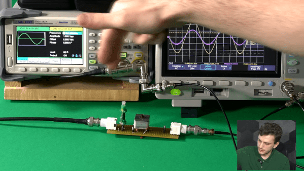
A man is shown on the left of the screen, speaking to the camera. On the right of the screen, a Smith chart is displayed. At the top of the screen, the words "TWO METHODS" are displayed.

A Gentle Introduction To Impedance Matching

Impedance matching is one of the perpetual confusions for new electronics students, and for good reason: the idea that increasing the impedance of a circuit can lead to more power transmission is frighteningly unintuitive at first glance. Even once you understand this, designing a circuit with impedance matching is a tricky task, and it’s here that [Ralph Gable]’s introduction to impedance matching is helpful.

The goal of impedance matching is to maximize the amount of power transmitted from a source to a load. In some simple situations, resistance is the only significant component in impedance, and it’s possible to match impedance just by matching resistance. In most situations, though, capacitance and inductance will add a reactive component to the impedance, in which case it becomes necessary to use the complex conjugate for impedance matching.

The video goes over this theory briefly, but it’s real focus is on explaining how to read a Smith chart, an intimidating-looking tool which can be used to calculate impedances. The video covers the basic impedance-only Smith chart, as well as a full-color Smith chart which indicates both impedance and admittance.

This video is the introduction to a planned series on impedance matching, and beyond reading Smith charts, it doesn’t really get into many specifics. However, based on the clear explanations so far, it could be worth waiting for the rest of the series.

If you’re interested in more practical details, we’ve also covered another example before. Continue reading “A Gentle Introduction To Impedance Matching”

The Physics Lesson I Keep Re-Learning

One of the most broadly applicable ideas I’ve ever encountered is the concept of impedance matching. If you’re into radio frequency electronics, you’re probably thinking that I mean getting all your circuit elements working to a common characteristic resistance for maximum power transfer. (If you’re not, you’re probably wondering what that jumble of words even means. Fear not!)

But I mean impedance matching in the larger sense. Think about driving a stick-shift automobile. In low gear, the engine has a lot of torque on the wheels, but it can’t spin them all that fast. In high, the wheels turn fastest, but there’s not enough torque to get you started from a standstill. Sometimes you need more force and less motion, other times more motion and less force. The gearbox lets you match the motor’s power to the resistance – the impedance – it’s trying to overcome.

Or think about a cello. The strings are tight, and vibrate with quite a bit of force, but they don’t move all that much. Air, which is destined to carry the sound to your ear, doesn’t take much force to move, and the cello would play louder if it moved more of it. So the bridge conveys the small, but strong, vibrations of the strings and pushes against the top of the resonant box that makes up the body of the instrument. This in turn pushes a lot of air, but not very hard. This is also why speakers have cones, and also why your ear has that crazy stirrup mechanism. Indeed, counting the number of impedance matches between Yo Yo Ma and your brain, I come up with four or five, including electrical matches in the pre-amp.

I mention this because I recently ran into a mismatch. Fans blow air either hard or in large volume. If you pick a fan that’s designed for volume, and put it in a pressure application, it’s like trying to start driving in fifth gear. It stalled, and almost no air got pushed up through the beans in my new “improved” coffee roaster, meaning I had to rebuild it with the old fan, and quick before the next cup was due.

I ran into this mismatch even though I knew there was a possible impedance issue there. I simply don’t have a good intuitive feel how much pressure I needed to push the beans around – the impedance in question – and I bought the wrong fan. But still, knowing that there is a trade-off is a good start. I hope this helps you avoid walking in my footsteps!

Input impedance plottet as a function of trace impedance for trace lengths of 1/10, 1/16 and 1/20 of a wavelength. (Credit: Baltic Labs)

When Does Impedance Matching A PCB Trace Become Unavoidable?

A common joke in electronics is that every piece of wire and PCB trace is an antenna, with the only difference being whether this was intentional or not. In practical terms, low-frequency wiring is generally considered to be ‘safe’, while higher frequency circuits require special considerations, including impedance (Z) matching.  Where the cut-off is between these two types of circuits is not entirely clear, however, with various rules-of-thumb in existence, as [Sebastian] over at Baltic Lab explains.

A popular rule is that no impedance matching between the trace and load is necessary if the critical length of a PCB trace (lcrit) is 1/10th of the wavelength (λ). Yet is this rule of thumb correct? Running through a number of calculations it’s obvious that the only case where the length of the PCB trace doesn’t matter is when trace and load impedance are matched.

According to these calculations, the 1/10 rule is not a great pick if your target is a mismatch loss of less than 0.1 dB, with 1/16 being a better rule. Making traces wider on the PCB can be advisable here, but ultimately you have to know what is best for your design, as each project has its own requirements. Even when the calculations look good, that’s no excuse to skip the measurement on the physical board, especially with how variable the dielectric constant of FR4 PCB material can be between different manufacturers and batches.

Heading image: Input impedance plotted as a function of trace impedance for trace lengths of 1/10, 1/16, and 1/20 of a wavelength. (Credit: Baltic Labs)

Continue reading “When Does Impedance Matching A PCB Trace Become Unavoidable?”

Impedance Matching Revisited

If you are an old hand at RF design, you probably have a good handle on matching impedance. However, if you are just getting started with RF, [FesZ Electronic]’s latest video series on lossless impedance matching is well worth watching.

Matching is important for several reasons. Maximum power transfer occurs when the source and load impedance match. Also, at RF, mismatched impedance can cause reflections which, again, robs you of useful power. The video covers some math and then moves on to LTSpice to simulate a test circuit. But the part you are really waiting for — the practical circuits — is about 15 minutes in. Since the values you need are often oddball, [FesZ] makes his own adjustable inductors and uses a trimmer capacitor to adjust the actual capacitance value.

This is a big topic, but the first video is a great introduction blending theory, simulation, and hands-on. A great way to get started with a very fundamental RF design skill.

We’ve worked on explaining all this before if you want a second take on it. If you want to understand why mismatched impedance leads to less power delivery, we’ve done that, too.

Continue reading “Impedance Matching Revisited”

Surplus Syringes Make Satisfactory Tuner For Amateur Radio Experimentation

Amateur Radio as a hobby has a long history of encouraging experimentation using whatever one might have on hand. When [Tom Essenpreis] wanted to use his 14 MHz antenna outside of its designed frequency range, he knew he’d need an impedance matching circuit. The most common type is an L-Match circuit which uses a variable capacitor and a variable inductor to adjust the usable frequency range (resonance) of an antenna. While inefficient in some specific configurations, they excel at bridging the gap between the 50 ohm impedance of the radio and the unknown impedance of an antenna.

No doubt raiding his junk box for parts, [Tom] hacked together a variable capacitor and inductor using ferrite rods from AM radios, hot glue, magnet wire, copper tape, and some surplus 60ml syringes. You can see that he ground out the center of the plunger to make room for ferrite rods. Winding the outside of the syringe with magnet wire, the alignment of the ferrite can be adjusted via the plunger, changing the characteristics of the element to tune the circuit. [Tom] reports that he was able to make an on-air contact using his newly made tuner, and we’re sure he enjoyed putting his improvised equipment to use.

If Amateur Radio isn’t your thing, then maybe we can entice you with this syringe based rocket, syringe actuated 3D printed drill press, or vacuum syringe powered dragster. Have your own hack to share? By all means, submit it to the Tip Line!

Bricking Your 3D Printer, In A Good Way

In our vernacular, bricking something is almost never good. It implies that something has gone very wrong indeed, and that your once-useful and likely expensive widget is now about as useful as a brick. Given their importance to civilization, that seems somewhat unfair to bricks, but it gets the point across.

It turns out, though, that bricks can play an important role in 3D-printing in terms of both noise control and print quality. As [Stefan] points out in the video below, living with a 3D printer whirring away on a long print can be disturbing, especially when the vibrations of the stepper motors are transmitted into and amplified by a solid surface, like a benchtop. He found that isolating the printer from the resonant surface was the key. While the stock felt pad feet on his Original Prusa i3 Mk 3S helped, the best results were achieved by building a platform of closed-cell packing foam and a concrete paver block. The combination of the springy foam and the dampening mass of the paver brought the sound level down almost 8 dBA.

[Stefan] also thoughtfully tested his setups on print quality. Machine tools generally perform better with more mass to damp unwanted vibration, so it stands to reason that perching a printer on top of a heavy concrete slab would improve performance. Even though the difference in quality wasn’t huge, it was noticeable, and coupled with the noise reduction, it makes the inclusion of a paver and some scraps of foam into your printing setup a no-brainer.

Not content to spend just a couple of bucks on a paver for vibration damping? Then cast a composite epoxy base for your machine — either with aluminum or with granite.

Continue reading “Bricking Your 3D Printer, In A Good Way”

Say It With Me: Input Impedance

In the “Say It with Me” series, we’ll take a commonly used concept out of electronics and explain it the best we can. If there’s something that’s been bugging you, or a certain term or concept that keeps cropping up in your projects, let us know. We’ll write about it!

What’s up with input impedance? You hear people talking about it, but why does it matter? And impedance matching? Let’s break it all down.

First of all, impedance is the frequency-dependent sister of resistance, so for intuition we’ll first work through the cases of purely resistive impedance. And that’s almost fine if you’re only ever working at one frequency. We’ll hint at the full-blown impedance = resistance + reactance version at the end, but it’s really its own topic. For now, pretend that your circuits aren’t reactive.

Continue reading “Say It With Me: Input Impedance”